How to Use plc: Examples, Pinouts, and Specs
Introduction
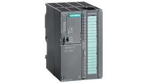
A Programmable Logic Controller (PLC) is a specialized digital computer designed for the automation and control of industrial processes and machinery. It is a robust, versatile, and flexible component that can handle multiple inputs and outputs, and is programmed to perform a wide range of tasks such as sequencing, timing, counting, and arithmetic to control complex machinery and processes. PLCs are essential in industries such as manufacturing, power generation, and infrastructure management, where they contribute to efficiency, precision, and reliability.
Explore Projects Built with plc

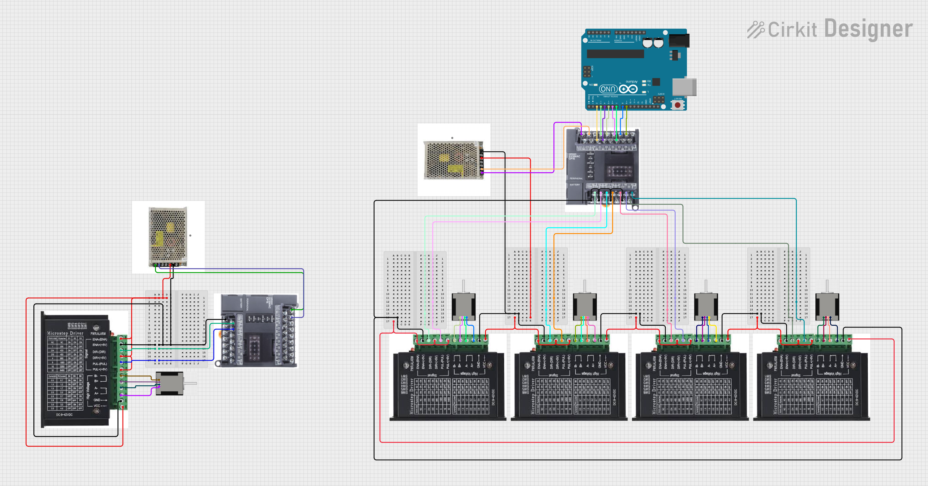

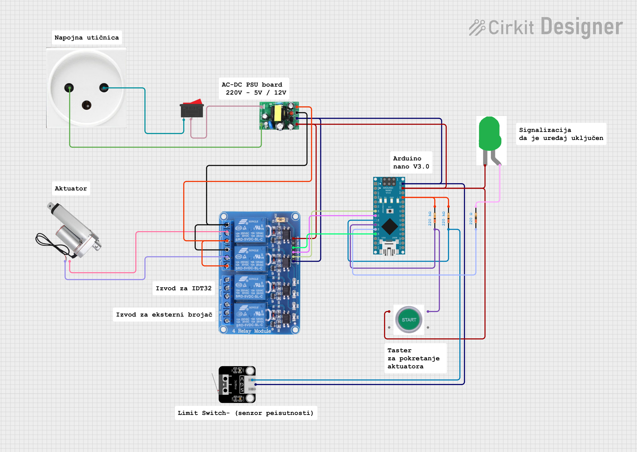
Explore Projects Built with plc
Common Applications and Use Cases
- Automated assembly lines
- Robotic devices
- Conveyor systems
- Material handling
- Process control in chemical plants
- Water treatment and distribution
- HVAC systems
Technical Specifications
Key Technical Details
| Specification | Description |
|---|---|
| Input Voltage | Typically 24V DC |
| Output Voltage | Depends on model; relay outputs usually 250V AC |
| Input/Output (I/O) Count | Varies by model; expandable with I/O modules |
| Communication Ports | Ethernet, RS-232, RS-485, etc. |
| Programming Languages | Ladder Logic, Function Block, Structured Text, etc. |
| Memory | Varies; sufficient for application program storage |
| Operating Temperature | -20°C to +60°C (typical range) |
Pin Configuration and Descriptions
Due to the complexity and variability of PLCs, pin configurations can vary widely between models and manufacturers. Below is a simplified representation of a generic PLC's I/O connections.
| Pin/Port | Description |
|---|---|
| Input 1-n | Digital/Analog inputs for sensors, switches, etc. |
| Output 1-n | Digital/Analog outputs to actuators, relays, etc. |
| COM | Common reference point for I/O circuits |
| GND | Ground connection |
| V+ | Positive supply voltage for I/O |
| Ethernet | Communication port for networking |
| RS-232/485 | Serial communication port for peripherals |
Usage Instructions
How to Use the PLC in a Circuit
- Power Supply Connection: Connect the PLC to a suitable power source, ensuring that the supply voltage matches the PLC's requirements.
- Input/Output Wiring: Connect sensors, switches, and other input devices to the PLC's input terminals, and connect actuators or relays to the output terminals.
- Communication Setup: Establish communication with the PLC using the appropriate port (Ethernet, RS-232, RS-485) for programming and monitoring.
- Programming: Use the manufacturer's software to program the PLC. The program should be written in one of the PLC's supported languages, such as Ladder Logic or Structured Text.
- Testing: Test the PLC program with the connected inputs and outputs to ensure the desired operation is achieved.
Important Considerations and Best Practices
- Always follow the manufacturer's installation and wiring guidelines.
- Use proper shielding and grounding to minimize electrical noise and interference.
- Consider the environmental conditions where the PLC will operate, such as temperature, humidity, and exposure to contaminants.
- Implement proper safety measures, including circuit protection and emergency stop mechanisms.
- Regularly back up the PLC program and maintain documentation of the system configuration.
Troubleshooting and FAQs
Common Issues Users Might Face
- PLC not powering on: Check power supply connections and fuses.
- Inputs/Outputs not responding: Verify wiring, check for short circuits, and ensure proper configuration in the PLC program.
- Communication errors: Check communication settings, cables, and connectors.
Solutions and Tips for Troubleshooting
- Use diagnostic tools and software provided by the PLC manufacturer to identify and isolate issues.
- Monitor the PLC's status indicators and error messages for clues on the nature of the problem.
- Ensure that all software and firmware updates are applied.
FAQs
Q: Can I expand the number of I/O on my PLC? A: Yes, most PLCs can be expanded with additional I/O modules. Check compatibility with your specific model.
Q: How do I back up my PLC program? A: Use the PLC programming software to save a copy of the program to an external storage device.
Q: What should I do if I encounter an unknown error code? A: Refer to the PLC's manual for error code descriptions or contact the manufacturer's technical support.
Example Code for Arduino UNO Connection
// Example code for interfacing an Arduino UNO with a PLC for simple digital I/O control

// Define the Arduino pin connected to the PLC input
const int plcInputPin = 2;

// Define the Arduino pin connected to the PLC output
const int plcOutputPin = 13;

void setup() {
  // Configure the input pin
  pinMode(plcInputPin, INPUT);

  // Configure the output pin
  pinMode(plcOutputPin, OUTPUT);
}

void loop() {
  // Read the state of the PLC input
  int plcInputState = digitalRead(plcInputPin);

  // If the PLC input is HIGH, set the output to HIGH
  if (plcInputState == HIGH) {
    digitalWrite(plcOutputPin, HIGH);
  } else {
    // If the PLC input is LOW, set the output to LOW
    digitalWrite(plcOutputPin, LOW);
  }
}
Note: This example assumes a simple digital input from the PLC to the Arduino and a digital output from the Arduino to the PLC. Actual implementation will vary based on the specific PLC and application requirements. Always refer to the PLC and Arduino manuals for proper connection and programming practices.