Cirkit Designer Logo
Cirkit Designer
Your all-in-one circuit design IDE
Home / 
Component Documentation

How to Use PowerBoost 500 Charger Terminal: Examples, Pinouts, and Specs

Image of PowerBoost 500 Charger Terminal
Cirkit Designer LogoDesign with PowerBoost 500 Charger Terminal in Cirkit Designer

Introduction

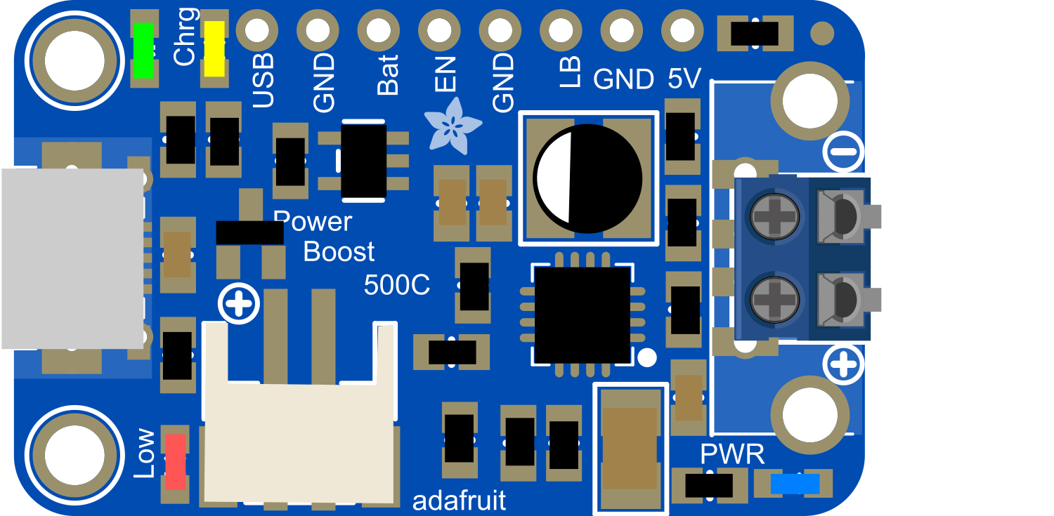
The PowerBoost 500 Charger Terminal is a versatile electronic component that integrates a battery charging circuit with a boost converter to provide a regulated 5V output from a lower voltage input source. This component is ideal for portable electronics, DIY projects, and any application requiring a stable 5V supply that can be charged and powered simultaneously.

Explore Projects Built with PowerBoost 500 Charger Terminal

Use Cirkit Designer to design, explore, and prototype these projects online. Some projects support real-time simulation. Click "Open Project" to start designing instantly!
Battery-Powered Lora G2 Node Station with 18650 Li-ion Batteries and Boost Converter
Image of Custom-Lora-G2-Node: A project utilizing PowerBoost 500 Charger Terminal in a practical application
This circuit is a portable power supply system that uses multiple 18650 Li-ion batteries to provide a stable 5V output through a boost converter. It includes a fast charging module with a USB-C input for recharging the batteries and a battery indicator for monitoring the battery status. The system powers a Lora G2 Node Station, making it suitable for wireless communication applications.
Cirkit Designer LogoOpen Project in Cirkit Designer
Battery-Powered 18650 Li-ion Charger with USB Output and Adjustable Voltage Regulator
Image of Breadboard: A project utilizing PowerBoost 500 Charger Terminal in a practical application
This circuit is a battery management and power supply system that uses three 3.7V batteries connected to a 3S 10A Li-ion 18650 Charger Protection Board Module for balanced charging and protection. The system includes a TP4056 Battery Charging Protection Module for additional charging safety, a Step Up Boost Power Converter to regulate and boost the voltage, and a USB regulator to provide a stable 5V output, controlled by a push switch.
Cirkit Designer LogoOpen Project in Cirkit Designer
Battery-Powered Raspberry Pi 3B+ with TP4056 and DC/DC Booster
Image of raspberry power supply: A project utilizing PowerBoost 500 Charger Terminal in a practical application
This circuit is a portable power supply system that charges a 18650 Li-ion battery using a TP4056 charging module and boosts the voltage to power a Raspberry Pi 3b+ via a DC/DC booster. The TP4056 module manages the charging of the battery, while the DC/DC booster converts the battery voltage to a stable 5V output for the Raspberry Pi.
Cirkit Designer LogoOpen Project in Cirkit Designer
Battery-Powered DC Motor Control with USB Charging and LED Indicator
Image of lumantas: A project utilizing PowerBoost 500 Charger Terminal in a practical application
This circuit is designed to charge a Li-ion battery and power a DC motor and a 12V LED. The TP4056 module manages the battery charging process, while the PowerBoost 1000 and MT3608 boost converters step up the voltage to drive the motor and LED, respectively. Two rocker switches control the power flow to the LED and the charging circuit.
Cirkit Designer LogoOpen Project in Cirkit Designer

Explore Projects Built with PowerBoost 500 Charger Terminal

Use Cirkit Designer to design, explore, and prototype these projects online. Some projects support real-time simulation. Click "Open Project" to start designing instantly!
Image of Custom-Lora-G2-Node: A project utilizing PowerBoost 500 Charger Terminal in a practical application
Battery-Powered Lora G2 Node Station with 18650 Li-ion Batteries and Boost Converter
This circuit is a portable power supply system that uses multiple 18650 Li-ion batteries to provide a stable 5V output through a boost converter. It includes a fast charging module with a USB-C input for recharging the batteries and a battery indicator for monitoring the battery status. The system powers a Lora G2 Node Station, making it suitable for wireless communication applications.
Cirkit Designer LogoOpen Project in Cirkit Designer
Image of Breadboard: A project utilizing PowerBoost 500 Charger Terminal in a practical application
Battery-Powered 18650 Li-ion Charger with USB Output and Adjustable Voltage Regulator
This circuit is a battery management and power supply system that uses three 3.7V batteries connected to a 3S 10A Li-ion 18650 Charger Protection Board Module for balanced charging and protection. The system includes a TP4056 Battery Charging Protection Module for additional charging safety, a Step Up Boost Power Converter to regulate and boost the voltage, and a USB regulator to provide a stable 5V output, controlled by a push switch.
Cirkit Designer LogoOpen Project in Cirkit Designer
Image of raspberry power supply: A project utilizing PowerBoost 500 Charger Terminal in a practical application
Battery-Powered Raspberry Pi 3B+ with TP4056 and DC/DC Booster
This circuit is a portable power supply system that charges a 18650 Li-ion battery using a TP4056 charging module and boosts the voltage to power a Raspberry Pi 3b+ via a DC/DC booster. The TP4056 module manages the charging of the battery, while the DC/DC booster converts the battery voltage to a stable 5V output for the Raspberry Pi.
Cirkit Designer LogoOpen Project in Cirkit Designer
Image of lumantas: A project utilizing PowerBoost 500 Charger Terminal in a practical application
Battery-Powered DC Motor Control with USB Charging and LED Indicator
This circuit is designed to charge a Li-ion battery and power a DC motor and a 12V LED. The TP4056 module manages the battery charging process, while the PowerBoost 1000 and MT3608 boost converters step up the voltage to drive the motor and LED, respectively. Two rocker switches control the power flow to the LED and the charging circuit.
Cirkit Designer LogoOpen Project in Cirkit Designer

Common Applications and Use Cases

  • Portable USB chargers
  • Battery-powered electronics
  • Wearable devices
  • DIY projects requiring a 5V supply
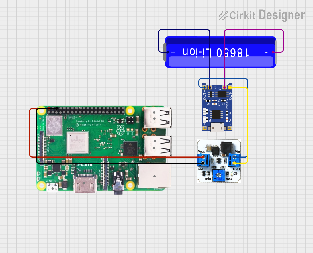
  • Raspberry Pi or Arduino portable projects

Technical Specifications

Key Technical Details

  • Input Voltage: 1.8V to 5.5V
  • Output Voltage: 5V regulated
  • Output Current: Up to 500mA with a 3.7V LiPo battery
  • Integrated charging circuit for 3.7V LiPo batteries
  • Charging Current: 500mA (max)
  • Battery Connector: JST-PH 2-pin
  • USB Micro B connector for charging input

Pin Configuration and Descriptions

Pin Number Name Description
1 USB 5V USB input voltage (5V from USB port)
2 GND Ground
3 Bat Battery input (3.7V LiPo)
4 5V Regulated 5V output
5 EN Enable pin (pull low to disable, float to enable)
6 LBO Low Battery Output (active low)

Usage Instructions

How to Use the Component in a Circuit

  1. Connect a 3.7V LiPo battery to the 'Bat' pin.
  2. Attach the device that requires 5V to the '5V' and 'GND' pins.
  3. To charge the battery, connect a USB Micro B cable to the USB port.
  4. The 'EN' pin can be left floating to enable the boost converter or pulled low to disable it.
  5. Monitor the 'LBO' pin; when it goes low, the battery is near depletion.

Important Considerations and Best Practices

  • Ensure the polarity of the battery is correct to prevent damage.
  • Do not exceed the input voltage range to avoid damaging the component.
  • Avoid drawing more than 500mA from the 5V output to maintain voltage regulation.
  • Use a multimeter to verify output voltage before connecting sensitive electronics.
  • Keep the 'EN' pin accessible in your design if you wish to control the power state.

Troubleshooting and FAQs

Common Issues

  • No Output Voltage: Ensure the battery is charged and properly connected. Check the USB power source and the 'EN' pin state.
  • Device Resets or Brown-Out: This may occur if the output current exceeds 500mA. Reduce the load or check for shorts.
  • Battery Not Charging: Verify the USB power source is functional and capable of supplying at least 500mA.

Solutions and Tips for Troubleshooting

  • If the output voltage is unstable or too low, check the battery and load conditions.
  • For charging issues, try a different USB cable or power source.
  • If the 'LBO' pin is active, recharge the battery as soon as possible.

FAQs

Q: Can I use the PowerBoost 500 Charger Terminal with batteries other than LiPo? A: It is designed specifically for 3.7V LiPo batteries. Using other types may not be safe or effective.

Q: What should I do if the PowerBoost 500 Charger Terminal overheats? A: Disconnect all power sources and loads immediately. Overheating may indicate a short circuit or overcurrent condition.

Q: Can I connect multiple devices to the 5V output? A: Yes, as long as the total current draw does not exceed 500mA.

Example Arduino UNO Connection

// No specific code is required for basic operation with Arduino UNO.
// Simply connect the 5V and GND outputs from the PowerBoost to the 5V and GND pins on the Arduino.

// If you want to monitor the battery status using an Arduino, you can connect the LBO pin to an Arduino digital pin.

const int lowBatteryPin = 2; // Connect LBO to digital pin 2 on Arduino

void setup() {
  pinMode(lowBatteryPin, INPUT_PULLUP); // Enable internal pull-up resistor
  Serial.begin(9600);
}

void loop() {
  // Check the status of the low battery indicator
  if (digitalRead(lowBatteryPin) == LOW) {
    // Low battery indicator is active
    Serial.println("Battery is low!");
  } else {
    // Battery level is okay
    Serial.println("Battery level is good.");
  }
  delay(1000); // Wait for 1 second before checking again
}

Remember to keep code comments concise and within the 80 character line limit.