How to Use MH-ET live Scanner: Examples, Pinouts, and Specs
Introduction
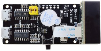
The MH-ET Live Scanner (AGE V3.0) is a versatile device designed for real-time monitoring and analysis of electrical signals in circuits. It provides users with valuable insights into circuit performance, enabling the identification of potential issues such as signal distortion, noise, or irregularities. This component is particularly useful for debugging, testing, and optimizing electronic designs.
Explore Projects Built with MH-ET live Scanner
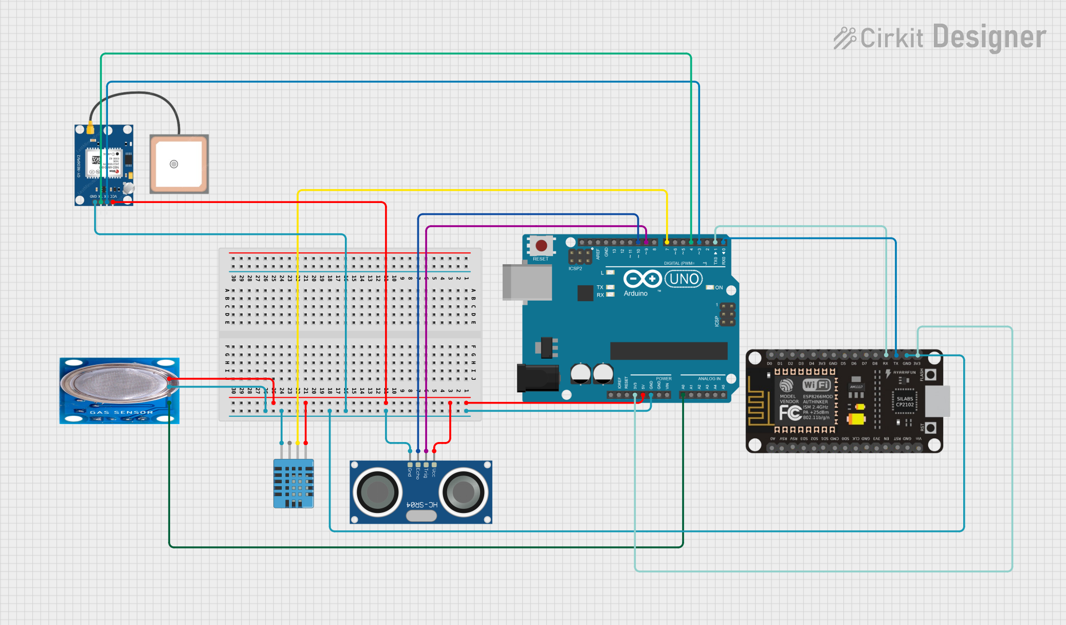
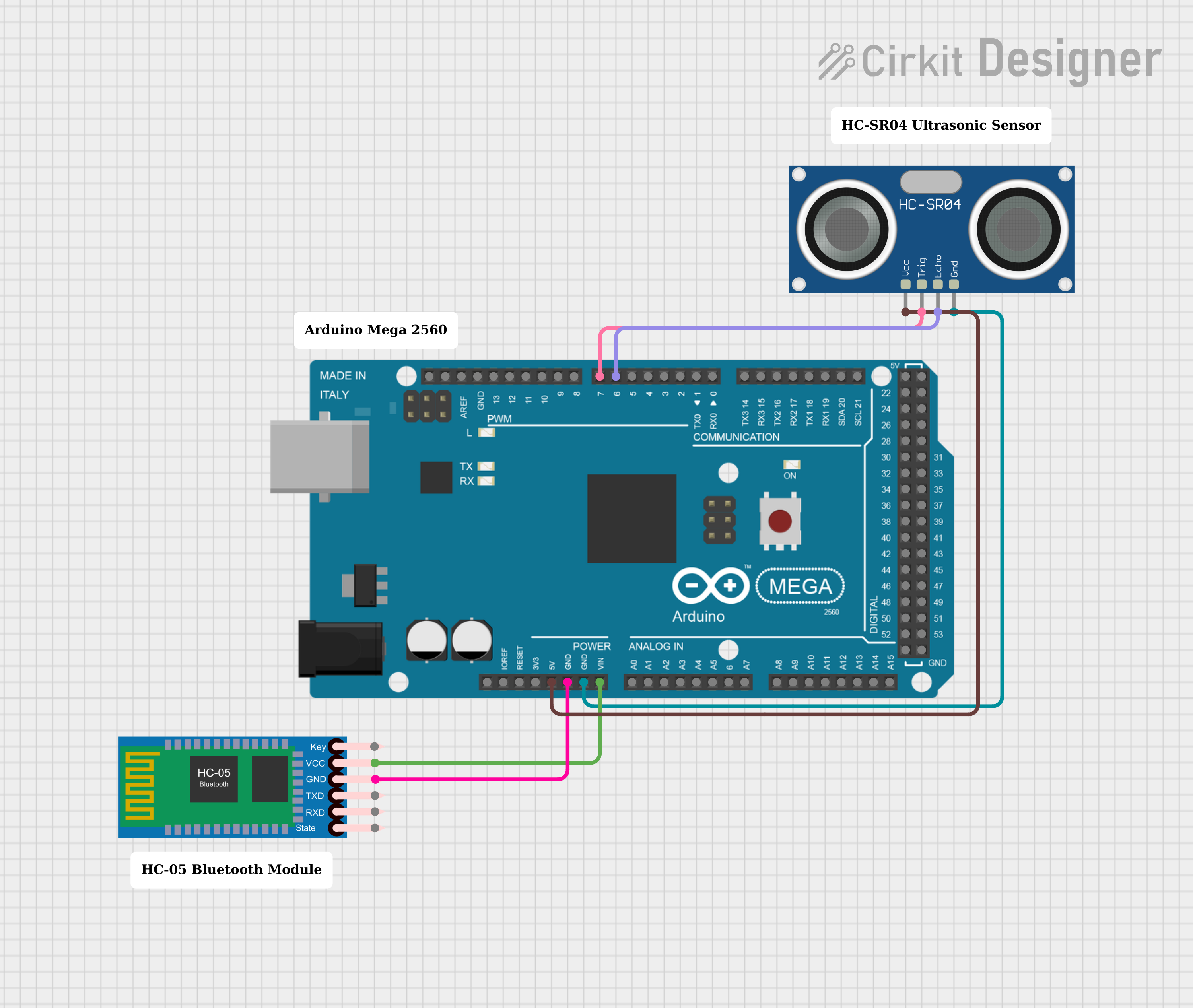
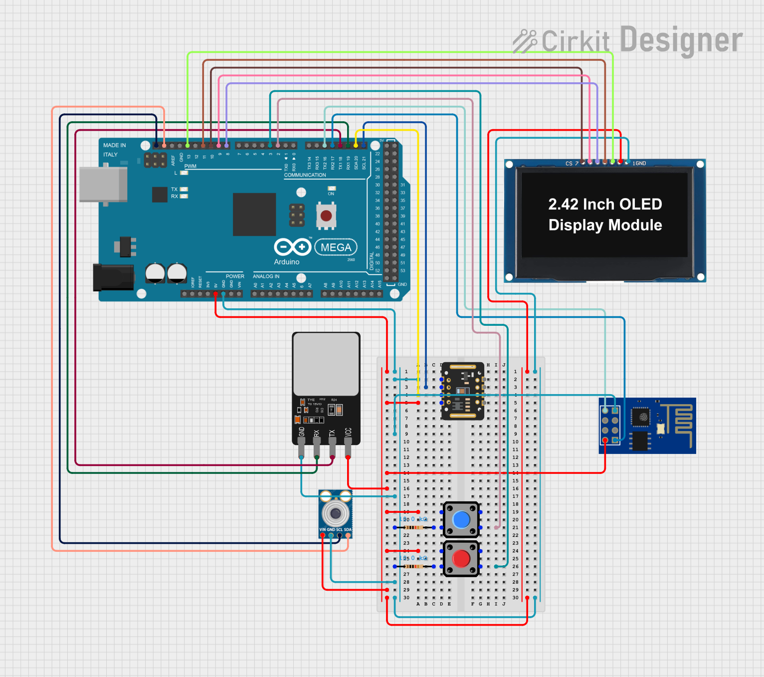
Explore Projects Built with MH-ET live Scanner
Common Applications and Use Cases
- Debugging and troubleshooting electronic circuits
- Monitoring signal integrity in real-time
- Educational purposes for understanding signal behavior
- Performance analysis of analog and digital circuits
- Integration with microcontroller platforms like Arduino for advanced projects
Technical Specifications
The following table outlines the key technical details of the MH-ET Live Scanner:
| Parameter | Specification |
|---|---|
| Manufacturer | AGE |
| Part ID | V3.0 |
| Operating Voltage | 3.3V to 5V DC |
| Input Signal Range | 0V to 5V |
| Sampling Rate | Up to 1 MSPS (Mega Samples Per Second) |
| Communication Protocol | UART (9600 baud rate default) |
| Dimensions | 40mm x 20mm x 10mm |
| Operating Temperature | -20°C to 70°C |
Pin Configuration and Descriptions
The MH-ET Live Scanner has a simple pinout for easy integration into circuits. The pin configuration is as follows:
| Pin | Name | Description |
|---|---|---|
| 1 | VCC | Power supply input (3.3V to 5V DC) |
| 2 | GND | Ground connection |
| 3 | RX | UART Receive pin for communication |
| 4 | TX | UART Transmit pin for communication |
| 5 | SIG_IN | Signal input pin for monitoring (0V to 5V range) |
Usage Instructions
How to Use the Component in a Circuit
- Power the Device: Connect the
VCCpin to a 3.3V or 5V DC power source and theGNDpin to the ground of your circuit. - Signal Input: Connect the signal you want to monitor to the
SIG_INpin. Ensure the signal voltage does not exceed the 0V to 5V range. - Communication: Use the
RXandTXpins to interface with a microcontroller or computer via UART. The default baud rate is 9600. - Data Visualization: Use a compatible software tool or microcontroller to read and visualize the signal data in real-time.
Important Considerations and Best Practices
- Signal Voltage Range: Ensure the input signal voltage remains within the 0V to 5V range to avoid damaging the device.
- Power Supply: Use a stable power source to prevent noise or fluctuations in the signal readings.
- UART Configuration: Configure the UART communication settings (baud rate, parity, etc.) correctly to ensure reliable data transmission.
- Signal Conditioning: For noisy or high-frequency signals, consider using external filters or amplifiers to improve measurement accuracy.
Example: Connecting to an Arduino UNO
The MH-ET Live Scanner can be easily connected to an Arduino UNO for signal monitoring. Below is an example setup and code:
Wiring
| MH-ET Live Scanner Pin | Arduino UNO Pin |
|---|---|
| VCC | 5V |
| GND | GND |
| RX | Pin 10 (via voltage divider if using 5V logic) |
| TX | Pin 11 |
| SIG_IN | Signal source |
Arduino Code
// Include SoftwareSerial library for UART communication
#include <SoftwareSerial.h>

// Define RX and TX pins for SoftwareSerial
SoftwareSerial LiveScanner(10, 11); // RX = Pin 10, TX = Pin 11

void setup() {
  // Initialize serial communication with the Live Scanner
  LiveScanner.begin(9600); // Set baud rate to 9600
  Serial.begin(9600);      // For debugging via Serial Monitor

  // Print initialization message
  Serial.println("MH-ET Live Scanner Initialized");
}

void loop() {
  // Check if data is available from the Live Scanner
  if (LiveScanner.available()) {
    // Read and print the data to the Serial Monitor
    String signalData = LiveScanner.readString();
    Serial.println("Signal Data: " + signalData);
  }

  // Add a small delay to avoid flooding the Serial Monitor
  delay(100);
}
Troubleshooting and FAQs
Common Issues and Solutions
No Signal Data Received
- Cause: Incorrect UART connection or baud rate mismatch.
- Solution: Verify the RX and TX connections and ensure the baud rate is set to 9600.
Distorted or Inaccurate Signal Readings
- Cause: Input signal exceeds the 0V to 5V range or is too noisy.
- Solution: Use a voltage divider or signal conditioning circuit to bring the signal within range.
Device Not Powering On
- Cause: Insufficient or unstable power supply.
- Solution: Ensure the
VCCpin is connected to a stable 3.3V or 5V source.
UART Communication Errors
- Cause: Incorrect UART settings or interference.
- Solution: Double-check the UART configuration and minimize electrical noise near the device.
FAQs
Q1: Can the MH-ET Live Scanner handle AC signals?
A1: Yes, the device can monitor AC signals, but the signal must remain within the 0V to 5V range. Use a coupling capacitor if necessary.
Q2: Is the device compatible with 3.3V logic microcontrollers?
A2: Yes, the MH-ET Live Scanner is fully compatible with 3.3V logic levels.
Q3: Can I use the device with other communication protocols?
A3: No, the MH-ET Live Scanner only supports UART communication.
Q4: What software can I use to visualize the signal data?
A4: You can use any serial terminal software (e.g., Arduino Serial Monitor, PuTTY) or custom software that supports UART communication.
By following this documentation, users can effectively integrate and utilize the MH-ET Live Scanner in their projects for real-time signal monitoring and analysis.