How to Use Active Balancer LiFePO4 4S 6A: Examples, Pinouts, and Specs
Introduction
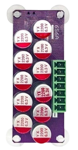
The Active Balancer LiFePO4 4S 6A is a specialized device designed to balance the charge across a series of four lithium iron phosphate (LiFePO4) cells in a battery pack. By ensuring that each cell maintains an equal voltage level, this balancer enhances the overall performance, safety, and lifespan of the battery pack. It supports a maximum balancing current of 6A, making it suitable for high-performance applications.
Explore Projects Built with Active Balancer LiFePO4 4S 6A


Explore Projects Built with Active Balancer LiFePO4 4S 6A
Common Applications and Use Cases
- Electric vehicles (EVs) and hybrid vehicles
- Solar energy storage systems
- Uninterruptible power supplies (UPS)
- Portable power stations
- Robotics and industrial equipment
Technical Specifications
The following table outlines the key technical details of the Active Balancer LiFePO4 4S 6A:
| Parameter | Value |
|---|---|
| Supported Battery Type | LiFePO4 (Lithium Iron Phosphate) |
| Number of Cells | 4 (4S configuration) |
| Maximum Balancing Current | 6A |
| Operating Voltage Range | 3.0V to 3.6V per cell |
| Balancing Accuracy | ±0.01V |
| Operating Temperature | -20°C to 60°C |
| Dimensions | 60mm x 40mm x 10mm |
| Weight | 30g |
Pin Configuration and Descriptions
The Active Balancer LiFePO4 4S 6A has a connector with the following pin configuration:
| Pin Number | Label | Description |
|---|---|---|
| 1 | B- | Negative terminal of the battery pack |
| 2 | B1 | Positive terminal of Cell 1 |
| 3 | B2 | Positive terminal of Cell 2 |
| 4 | B3 | Positive terminal of Cell 3 |
| 5 | B4 | Positive terminal of Cell 4 |
| 6 | B+ | Positive terminal of the battery pack |
Usage Instructions
How to Use the Component in a Circuit
Wiring the Balancer:
- Connect the
B-pin to the negative terminal of the battery pack. - Connect the
B1,B2,B3, andB4pins to the positive terminals of Cells 1, 2, 3, and 4, respectively. - Connect the
B+pin to the positive terminal of the battery pack. - Ensure all connections are secure and free of short circuits.
- Connect the
Powering On:
- Once connected, the balancer will automatically begin monitoring and balancing the cells.
- The device will redistribute charge from higher-voltage cells to lower-voltage cells to equalize the voltage levels.
Monitoring:
- Some models may include indicator LEDs or external monitoring interfaces to display the balancing status. Refer to the specific model's datasheet for details.
Important Considerations and Best Practices
- Voltage Range: Ensure that the voltage of each cell remains within the operating range of 3.0V to 3.6V. Operating outside this range may damage the balancer or the cells.
- Connection Order: Always connect the balancer to the battery pack in the correct order (B-, B1, B2, B3, B4, B+). Incorrect wiring can cause malfunction or damage.
- Heat Dissipation: During operation, the balancer may generate heat. Ensure adequate ventilation or heat sinking to prevent overheating.
- Avoid Overcurrent: Do not exceed the maximum balancing current of 6A. Doing so may damage the device.
Arduino Integration Example
While the Active Balancer LiFePO4 4S 6A operates autonomously, you can monitor the cell voltages using an Arduino UNO and a voltage divider circuit. Below is an example code snippet for reading the voltages of the four cells:
// Example code to monitor LiFePO4 cell voltages using Arduino UNO
// Ensure proper voltage dividers are used to step down cell voltages to <5V

const int cell1Pin = A0; // Analog pin for Cell 1
const int cell2Pin = A1; // Analog pin for Cell 2
const int cell3Pin = A2; // Analog pin for Cell 3
const int cell4Pin = A3; // Analog pin for Cell 4

void setup() {
  Serial.begin(9600); // Initialize serial communication
}

void loop() {
  // Read analog values from each cell
  int cell1Raw = analogRead(cell1Pin);
  int cell2Raw = analogRead(cell2Pin);
  int cell3Raw = analogRead(cell3Pin);
  int cell4Raw = analogRead(cell4Pin);

  // Convert raw values to voltages (adjust for your voltage divider ratio)
  float cell1Voltage = cell1Raw * (5.0 / 1023.0) * 2; // Example: Divider ratio = 2
  float cell2Voltage = cell2Raw * (5.0 / 1023.0) * 2;
  float cell3Voltage = cell3Raw * (5.0 / 1023.0) * 2;
  float cell4Voltage = cell4Raw * (5.0 / 1023.0) * 2;

  // Print voltages to the Serial Monitor
  Serial.print("Cell 1 Voltage: ");
  Serial.println(cell1Voltage);
  Serial.print("Cell 2 Voltage: ");
  Serial.println(cell2Voltage);
  Serial.print("Cell 3 Voltage: ");
  Serial.println(cell3Voltage);
  Serial.print("Cell 4 Voltage: ");
  Serial.println(cell4Voltage);

  delay(1000); // Wait 1 second before the next reading
}
Troubleshooting and FAQs
Common Issues and Solutions
The balancer is not balancing the cells.
- Solution: Check the wiring to ensure all connections are correct and secure. Verify that the cell voltages are within the operating range (3.0V to 3.6V).
The balancer is overheating.
- Solution: Ensure proper ventilation or add a heat sink to dissipate heat. Avoid exceeding the maximum balancing current of 6A.
One cell remains unbalanced.
- Solution: Verify the voltage of the problematic cell. If it is significantly lower than the others, manually charge it to bring it closer to the others before using the balancer.
The balancer is not powering on.
- Solution: Check the battery pack voltage and ensure it is within the supported range. Inspect all connections for continuity.
FAQs
Q: Can this balancer be used with other battery chemistries?
A: No, this balancer is specifically designed for LiFePO4 cells. Using it with other chemistries may result in improper operation or damage.
Q: Does the balancer require an external power source?
A: No, the balancer draws power directly from the connected battery pack.
Q: Can I use this balancer with more than four cells?
A: No, this model is designed for a 4S configuration only. For more cells, consider a balancer designed for higher cell counts.
Q: How do I know if the balancer is working?
A: Some models include indicator LEDs to show balancing activity. Alternatively, you can measure the cell voltages to confirm they are equalizing over time.