Cirkit Designer Logo
Cirkit Designer
Your all-in-one circuit design IDE
Home / 
Component Documentation

How to Use Adafruit DC+Stepper FeatherWing: Examples, Pinouts, and Specs

Image of Adafruit DC+Stepper FeatherWing
Cirkit Designer LogoDesign with Adafruit DC+Stepper FeatherWing in Cirkit Designer

Introduction

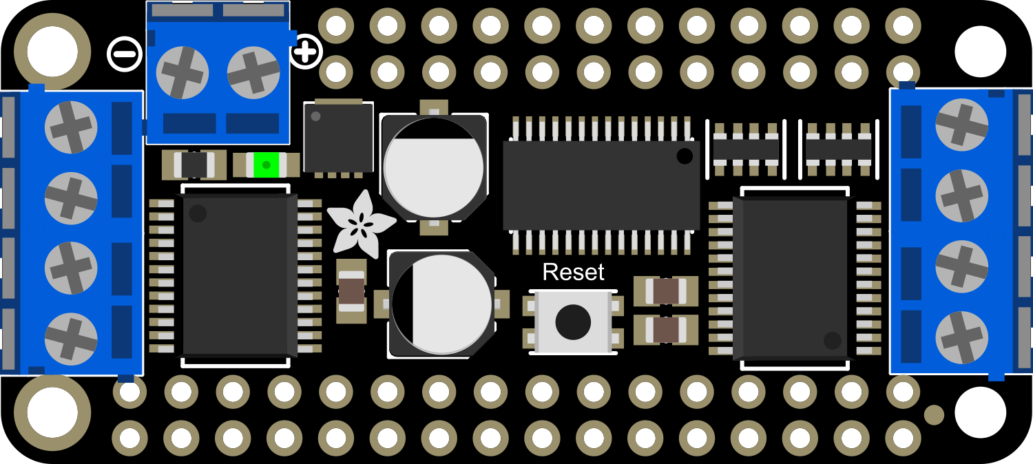
The Adafruit DC+Stepper FeatherWing is a versatile motor driver add-on board designed for use with the Adafruit Feather development boards. This component allows users to control up to 2 stepper motors or 4 DC motors with PWM speed control. It is an ideal choice for hobbyists and engineers who are looking to create projects that require precise motor control, such as robotic arms, automated tools, or custom vehicles.

Explore Projects Built with Adafruit DC+Stepper FeatherWing

Use Cirkit Designer to design, explore, and prototype these projects online. Some projects support real-time simulation. Click "Open Project" to start designing instantly!
Arduino UNO and Adafruit FeatherWing Controlled DC Motor System with RC Receiver
Image of Manta Bot: A project utilizing Adafruit DC+Stepper FeatherWing in a practical application
This circuit is a remote-controlled system that uses an Arduino UNO to interface with an RC receiver module and control four DC motors via an Adafruit DC+Stepper FeatherWing. The motors are powered by a 12V battery, and the system includes a rocker switch for power control.
Cirkit Designer LogoOpen Project in Cirkit Designer
ESP32-Based Vibration Feedback System with Quad Alphanumeric Display and ADXL343 Accelerometer
Image of EC444 - Quest 3: A project utilizing Adafruit DC+Stepper FeatherWing in a practical application
This circuit features an Adafruit HUZZAH32 ESP32 Feather board as the central microcontroller, which is connected to an Adafruit Quad AlphaNumeric Featherwing display and an Adafruit ADXL343 accelerometer via I2C communication (SCL and SDA lines). The ESP32 controls a vibration motor connected to one of its GPIO pins (A5_IO4) and shares a common power supply (3.3V) and ground (GND) with the other components. The purpose of this circuit is likely to read acceleration data, display information on the alphanumeric display, and provide haptic feedback through the vibration motor.
Cirkit Designer LogoOpen Project in Cirkit Designer
Wi-Fi Controlled Environmental Monitoring System with Dual Stepper Motor Valve Actuation
Image of MVP : A project utilizing Adafruit DC+Stepper FeatherWing in a practical application
This circuit features two 28BYJ-48 stepper motors controlled by ULN2003A breakout boards, interfaced with a NodeMCU V3 ESP8266 microcontroller. The NodeMCU collects environmental data from a DHT11 temperature and humidity sensor and an MQ-135 air quality sensor. The microcontroller uses WiFi for connectivity and controls the stepper motors based on the sensor inputs, likely for regulating environmental conditions.
Cirkit Designer LogoOpen Project in Cirkit Designer
Arduino Mega 2560 Controlled Multi-Stepper Motor System with DC Buck Step-down Power Supply
Image of Arduino Mega 2560 Controlled Stepper Motor System with DC Buck Step-down Power Supply: A project utilizing Adafruit DC+Stepper FeatherWing in a practical application
This circuit is a stepper motor control system powered by a DC Buck Step-down power supply and controlled by an Arduino Mega 2560. It uses TB6600 and A4988 stepper motor drivers along with ULN2003A breakout boards to drive multiple stepper motors. The Arduino code initializes the pins and provides basic control functionality for the stepper motors.
Cirkit Designer LogoOpen Project in Cirkit Designer

Explore Projects Built with Adafruit DC+Stepper FeatherWing

Use Cirkit Designer to design, explore, and prototype these projects online. Some projects support real-time simulation. Click "Open Project" to start designing instantly!
Image of Manta Bot: A project utilizing Adafruit DC+Stepper FeatherWing in a practical application
Arduino UNO and Adafruit FeatherWing Controlled DC Motor System with RC Receiver
This circuit is a remote-controlled system that uses an Arduino UNO to interface with an RC receiver module and control four DC motors via an Adafruit DC+Stepper FeatherWing. The motors are powered by a 12V battery, and the system includes a rocker switch for power control.
Cirkit Designer LogoOpen Project in Cirkit Designer
Image of EC444 - Quest 3: A project utilizing Adafruit DC+Stepper FeatherWing in a practical application
ESP32-Based Vibration Feedback System with Quad Alphanumeric Display and ADXL343 Accelerometer
This circuit features an Adafruit HUZZAH32 ESP32 Feather board as the central microcontroller, which is connected to an Adafruit Quad AlphaNumeric Featherwing display and an Adafruit ADXL343 accelerometer via I2C communication (SCL and SDA lines). The ESP32 controls a vibration motor connected to one of its GPIO pins (A5_IO4) and shares a common power supply (3.3V) and ground (GND) with the other components. The purpose of this circuit is likely to read acceleration data, display information on the alphanumeric display, and provide haptic feedback through the vibration motor.
Cirkit Designer LogoOpen Project in Cirkit Designer
Image of MVP : A project utilizing Adafruit DC+Stepper FeatherWing in a practical application
Wi-Fi Controlled Environmental Monitoring System with Dual Stepper Motor Valve Actuation
This circuit features two 28BYJ-48 stepper motors controlled by ULN2003A breakout boards, interfaced with a NodeMCU V3 ESP8266 microcontroller. The NodeMCU collects environmental data from a DHT11 temperature and humidity sensor and an MQ-135 air quality sensor. The microcontroller uses WiFi for connectivity and controls the stepper motors based on the sensor inputs, likely for regulating environmental conditions.
Cirkit Designer LogoOpen Project in Cirkit Designer
Image of Arduino Mega 2560 Controlled Stepper Motor System with DC Buck Step-down Power Supply: A project utilizing Adafruit DC+Stepper FeatherWing in a practical application
Arduino Mega 2560 Controlled Multi-Stepper Motor System with DC Buck Step-down Power Supply
This circuit is a stepper motor control system powered by a DC Buck Step-down power supply and controlled by an Arduino Mega 2560. It uses TB6600 and A4988 stepper motor drivers along with ULN2003A breakout boards to drive multiple stepper motors. The Arduino code initializes the pins and provides basic control functionality for the stepper motors.
Cirkit Designer LogoOpen Project in Cirkit Designer

Common Applications and Use Cases

  • Robotics
  • CNC machines
  • Automated art installations
  • Educational projects
  • Prototyping motor-driven mechanisms

Technical Specifications

Key Technical Details

  • Motor Voltage: 4.5V to 13.5V
  • Logic Voltage: 3V to 5V
  • Output Current: Up to 1.2A per channel (with proper heat-sinking, up to 3A peak)
  • PWM Frequency: 1.6 kHz

Pin Configuration and Descriptions

Pin Function Description
A1, A2 Motor A Terminals Connect to motor A or coil 1 of a stepper motor
B1, B2 Motor B Terminals Connect to motor B or coil 2 of a stepper motor
C1, C2 Motor C Terminals Connect to motor C (DC motor use only)
D1, D2 Motor D Terminals Connect to motor D (DC motor use only)
GND Ground Common ground for logic and motor power
VIN Motor Power Supply Input for motor power (4.5V to 13.5V)
3Vo Logic Power Output 3.3V output (from Feather board)
SDA, SCL I2C Data/Clock I2C communication pins
PWM PWM Input Pulse Width Modulation input for speed control

Usage Instructions

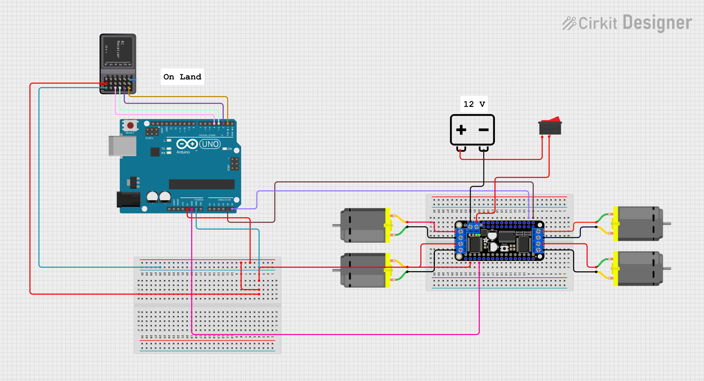
How to Use the Component in a Circuit

  1. Power Connections:

    • Connect the motor power supply to the VIN and GND terminals.
    • Ensure that the logic power is supplied from the Feather board to the 3Vo pin.
  2. Motor Connections:

    • Connect your DC or stepper motors to the appropriate terminals (A1, A2 for Motor A/Stepper Coil 1, etc.).
  3. Control Interface:

    • Use the I2C interface (SDA and SCL pins) to communicate with the FeatherWing from your Feather board.
  4. PWM Speed Control:

    • Apply PWM signals to the PWM pin for speed control of DC motors.

Important Considerations and Best Practices

  • Always ensure that the power supply voltage and current do not exceed the specified limits.
  • Use proper heat-sinking for currents above 1.2A per channel.
  • Avoid running motors at full speed for extended periods to prevent overheating.
  • When using stepper motors, ensure that the stepping sequence is correctly programmed for smooth operation.

Example Code for Arduino UNO

#include <Wire.h>
#include <Adafruit_MotorShield.h>

// Create the motor shield object with the default I2C address
Adafruit_MotorShield AFMS = Adafruit_MotorShield(); 

// Connect a stepper motor with 200 steps per revolution (1.8 degree)
// to motor port #2 (M3 and M4)
Adafruit_StepperMotor *myMotor = AFMS.getStepper(200, 2);

void setup() {
  Serial.begin(9600);           // Start serial communication.
  AFMS.begin();                 // Create with the default frequency 1.6KHz.
  
  myMotor->setSpeed(10);        // Set the speed to 10 rpm.
}

void loop() {
  myMotor->step(100, FORWARD, SINGLE); 
  Serial.println("Stepped 100 steps forward, single coil steps.");
  delay(1000);
}

Note: This example assumes the use of an Adafruit Motor Shield library, which may need to be modified for direct use with the FeatherWing. The code provided is for illustrative purposes and may require adjustments for specific Feather boards.

Troubleshooting and FAQs

Common Issues

  • Motor not responding: Check connections and ensure that the power supply is adequate.
  • Overheating: Ensure proper heat-sinking and avoid running motors at high currents for extended periods.
  • Inaccurate motor movement: Verify that the stepping sequence and speed settings are correct for stepper motors.

Solutions and Tips for Troubleshooting

  • Double-check wiring against the pin configuration table.
  • Use a multimeter to verify power supply voltage and motor resistance.
  • Review your code to ensure that the I2C address and motor configurations are correct.
  • Consult the Adafruit forums and support channels for assistance.

FAQs

Q: Can I control more than one FeatherWing at a time? A: Yes, you can stack multiple FeatherWings, but you will need to manage different I2C addresses for each one.

Q: What is the maximum number of motors I can control with one FeatherWing? A: You can control up to 4 DC motors or 2 stepper motors with a single FeatherWing.

Q: Can I use this FeatherWing with other development boards besides Feather? A: While designed for Feather boards, it is possible to use the FeatherWing with other development boards that support I2C communication and meet the logic voltage requirements. However, additional wiring and code adjustments may be necessary.