
How to Use PICAXE-28X2: Examples, Pinouts, and Specs
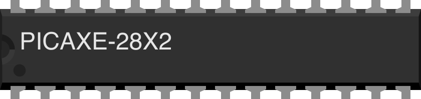
 Design with PICAXE-28X2 in Cirkit Designer
Introduction
The PICAXE-28X2 is a versatile microcontroller from the PICAXE family, featuring 28 pins and designed to run programs written in the BASIC programming language. It is widely used in educational environments and hobbyist projects due to its ease of use, built-in features, and affordability. The PICAXE-28X2 supports analog inputs, digital outputs, serial communication, and other advanced functionalities, making it suitable for a variety of applications.
Explore Projects Built with PICAXE-28X2
 Open Project in Cirkit Designer
 Open Project in Cirkit Designer
 Open Project in Cirkit Designer
 Open Project in Cirkit Designer
Explore Projects Built with PICAXE-28X2
Open Project in Cirkit DesignerOpen Project in Cirkit DesignerOpen Project in Cirkit DesignerOpen Project in Cirkit DesignerCommon Applications and Use Cases
- Robotics and automation projects
- Educational tools for learning microcontroller programming
- Sensor data acquisition and processing
- Home automation systems
- Prototyping and hobbyist electronics projects
Technical Specifications
The PICAXE-28X2 offers a range of features and capabilities that make it a powerful yet user-friendly microcontroller. Below are its key technical specifications:
| Specification | Details |
|---|---|
| Operating Voltage | 3V to 5.5V |
| Clock Speed | Up to 64 MHz (internal resonator) |
| Programming Language | BASIC (PICAXE-specific dialect) |
| Number of I/O Pins | 28 pins (16 digital I/O, 4 analog inputs, 8 configurable pins) |
| Memory | 4096 program lines (flash memory) |
| Communication Protocols | Serial (RS232), I2C, SPI |
| ADC Resolution | 10-bit (on analog input pins) |
| PWM Outputs | 4 channels |
| EEPROM | 256 bytes |
| Power Consumption | Low power mode available (nanoWatt technology) |
| Package Type | DIP-28 (Dual Inline Package) |
Pin Configuration and Descriptions
The PICAXE-28X2 has 28 pins, each with specific functions. Below is the pin configuration:
| Pin Number | Pin Name | Function |
|---|---|---|
| 1 | VSS | Ground (0V) |
| 2 | VDD | Positive supply voltage (3V to 5.5V) |
| 3 | Serial In | Serial programming input |
| 4 | Serial Out | Serial programming output |
| 5-12 | C.0 - C.7 | General-purpose I/O pins (digital or analog, depending on configuration) |
| 13-16 | B.0 - B.3 | General-purpose I/O pins (digital or PWM outputs) |
| 17-20 | A.0 - A.3 | Analog input pins (10-bit ADC resolution) |
| 21-28 | B.4 - B.7 | General-purpose I/O pins (digital or communication protocols like I2C/SPI) |
Usage Instructions
How to Use the PICAXE-28X2 in a Circuit
- Power Supply: Connect the VDD pin to a 3V-5.5V power source and the VSS pin to ground.
- Programming: Use the PICAXE programming cable to connect the Serial In and Serial Out pins to your computer. Write and upload your BASIC program using the PICAXE Editor software.
- I/O Configuration: Configure the pins as digital inputs, digital outputs, analog inputs, or communication pins based on your project requirements.
- Peripheral Connections: Connect sensors, actuators, or other peripherals to the appropriate pins. For example:
- Analog sensors to A.0 - A.3
- Digital devices to C.0 - C.7 or B.0 - B.7
- PWM-controlled devices (e.g., motors) to B.0 - B.3
Important Considerations and Best Practices
- Decoupling Capacitor: Place a 0.1 µF capacitor between VDD and VSS to stabilize the power supply.
- Pull-Down Resistors: Use pull-down resistors on unused input pins to prevent floating states.
- Programming Voltage: Ensure the programming voltage matches the microcontroller's operating voltage.
- Pin Protection: Avoid exceeding the maximum voltage or current ratings for any pin to prevent damage.
Example Code for Arduino-like Functionality
Below is an example of a simple program to read an analog sensor and control an LED using the PICAXE-28X2:
' Define pin constants
symbol sensorPin = A.0    ' Analog input pin for the sensor
symbol ledPin = B.0       ' Digital output pin for the LED

main:
    do
        ' Read the analog value from the sensor
        readadc10 sensorPin, w0  ' Store the 10-bit ADC value in variable w0

        ' Check if the sensor value exceeds a threshold
        if w0 > 512 then
            high ledPin          ' Turn on the LED if the threshold is exceeded
        else
            low ledPin           ' Turn off the LED otherwise
        endif

        pause 100                ' Wait for 100 milliseconds
    loop
Troubleshooting and FAQs
Common Issues and Solutions
The microcontroller does not respond to programming commands.
- Ensure the programming cable is securely connected to the Serial In and Serial Out pins.
- Verify that the PICAXE Editor software is configured for the correct COM port.
- Check the power supply voltage and ensure it is within the 3V-5.5V range.
Analog readings are unstable or incorrect.
- Use a decoupling capacitor near the analog input pins to reduce noise.
- Ensure the sensor connected to the analog pin is functioning correctly.
The microcontroller resets unexpectedly.
- Check for loose connections in the power supply or ground.
- Avoid drawing excessive current from the I/O pins.
PWM outputs are not working as expected.
- Verify that the pins used for PWM are correctly configured in the program.
- Ensure the connected device (e.g., motor or LED) is compatible with PWM signals.
FAQs
Q: Can the PICAXE-28X2 communicate with other microcontrollers?
A: Yes, the PICAXE-28X2 supports serial, I2C, and SPI communication protocols, allowing it to interface with other microcontrollers or devices.
Q: Is the PICAXE-28X2 suitable for battery-powered projects?
A: Yes, the PICAXE-28X2 has low power consumption and supports a wide operating voltage range, making it ideal for battery-powered applications.
Q: Can I use the PICAXE-28X2 with external crystals for precise timing?
A: Yes, the PICAXE-28X2 supports external crystals or resonators for applications requiring precise timing.
Q: What software is required to program the PICAXE-28X2?
A: The PICAXE Editor software, available for free on the PICAXE website, is used to write and upload programs to the microcontroller.