Cirkit Designer Logo
Cirkit Designer
Your all-in-one circuit design IDE
Home / 
Component Documentation

How to Use RTD PT100: Examples, Pinouts, and Specs

Image of RTD PT100
Cirkit Designer LogoDesign with RTD PT100 in Cirkit Designer

Introduction

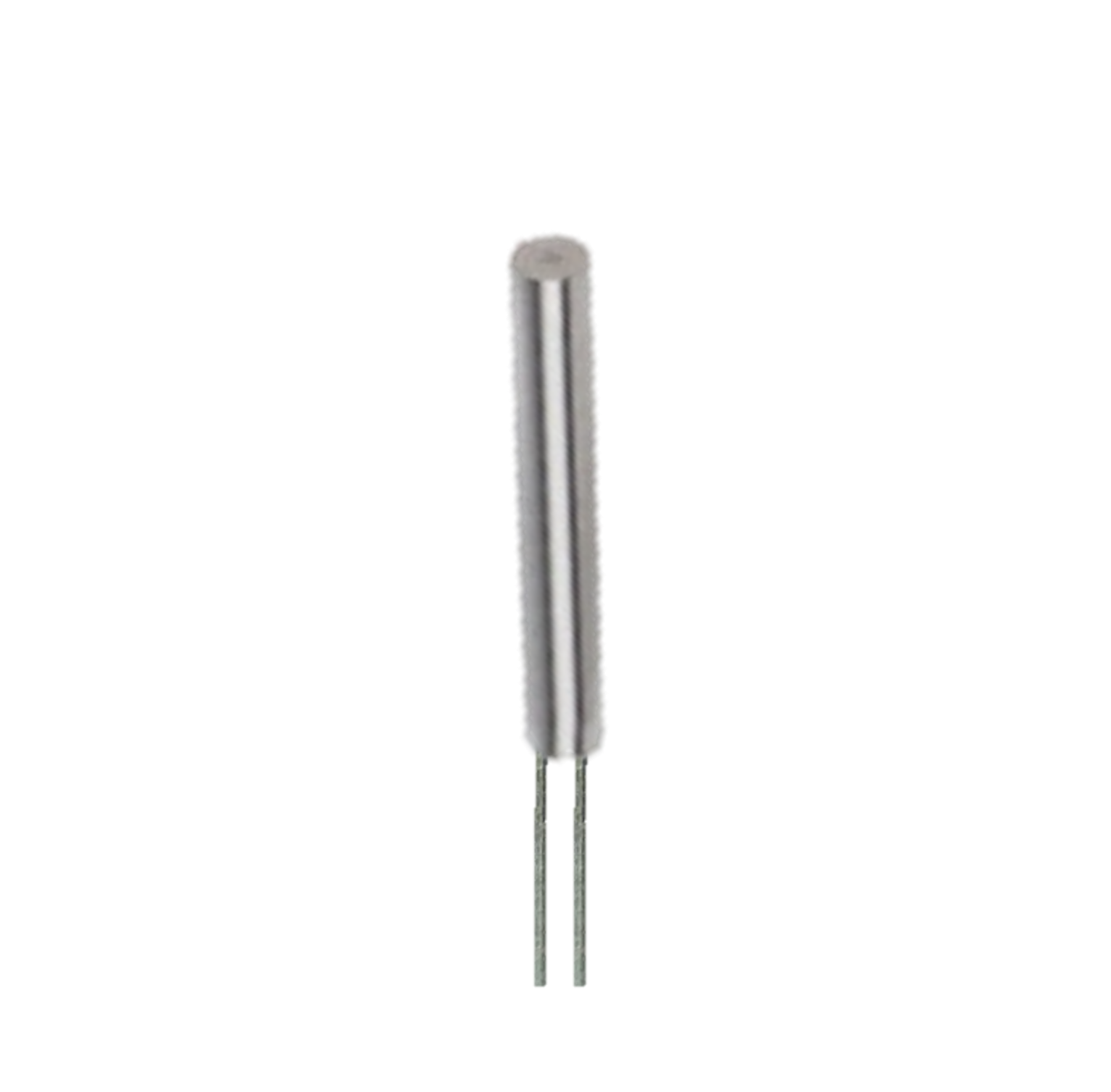
The RTD PT100 is a Resistance Temperature Detector that utilizes platinum (PT) with a resistance of 100 ohms at 0°C. It is widely used for precise temperature measurements due to its high accuracy and stability. The PT100 is commonly found in industrial applications, laboratory environments, and any scenario where accurate temperature monitoring is crucial.

Explore Projects Built with RTD PT100

Use Cirkit Designer to design, explore, and prototype these projects online. Some projects support real-time simulation. Click "Open Project" to start designing instantly!
Arduino Mega 2560 Based Temperature Monitoring and Relay Control System
Image of pepa: A project utilizing RTD PT100 in a practical application
This circuit is designed to measure temperature using a PT100 sensor interfaced with an Arduino Mega 2560 through an Adafruit MAX31865 RTD Sensor Breakout. The Arduino controls a relay based on the temperature threshold set via serial input and displays the temperature readings on an I2C LCD display. The relay can be used to control an external device, such as a heater or a fan, based on the temperature.
Cirkit Designer LogoOpen Project in Cirkit Designer
Arduino UNO and MAX31865 RTD Sensor Temperature Monitoring System with Dual Piezo Buzzers
Image of Alarmas: A project utilizing RTD PT100 in a practical application
This circuit is a temperature monitoring and alert system using an Arduino UNO. It includes an Adafruit MAX31865 RTD Sensor Breakout connected to an RTD PT100 for precise temperature measurements, and an NTC thermistor for additional temperature sensing. The system also features two piezo buzzers for audible alerts, controlled via resistors connected to the Arduino's digital pins.
Cirkit Designer LogoOpen Project in Cirkit Designer
Wi-Fi Enabled Temperature Monitoring System with NodeMCU and MAX31865
Image of temperature screening: A project utilizing RTD PT100 in a practical application
This circuit uses a NodeMCU V3 ESP8266 microcontroller to interface with an Adafruit MAX31865 RTD Sensor Breakout, which reads temperature data from an RTD PT100 sensor. The microcontroller processes the temperature data and outputs it via the serial interface, making it suitable for applications requiring precise temperature monitoring and logging.
Cirkit Designer LogoOpen Project in Cirkit Designer
ESP32-Based Temperature Monitoring System with OLED Display and LoRa Communication
Image of transfer: A project utilizing RTD PT100 in a practical application
This circuit features an ESP32 microcontroller connected to a 0.96" OLED display, a LoRa RA02 module for long-range communication, and an Adafruit MAX31865 RTD Sensor Breakout for temperature measurements using a PT100 RTD sensor. Three pushbuttons are interfaced with the ESP32 for user input. The circuit is designed for temperature monitoring with a display output and remote data transmission capabilities.
Cirkit Designer LogoOpen Project in Cirkit Designer

Explore Projects Built with RTD PT100

Use Cirkit Designer to design, explore, and prototype these projects online. Some projects support real-time simulation. Click "Open Project" to start designing instantly!
Image of pepa: A project utilizing RTD PT100 in a practical application
Arduino Mega 2560 Based Temperature Monitoring and Relay Control System
This circuit is designed to measure temperature using a PT100 sensor interfaced with an Arduino Mega 2560 through an Adafruit MAX31865 RTD Sensor Breakout. The Arduino controls a relay based on the temperature threshold set via serial input and displays the temperature readings on an I2C LCD display. The relay can be used to control an external device, such as a heater or a fan, based on the temperature.
Cirkit Designer LogoOpen Project in Cirkit Designer
Image of Alarmas: A project utilizing RTD PT100 in a practical application
Arduino UNO and MAX31865 RTD Sensor Temperature Monitoring System with Dual Piezo Buzzers
This circuit is a temperature monitoring and alert system using an Arduino UNO. It includes an Adafruit MAX31865 RTD Sensor Breakout connected to an RTD PT100 for precise temperature measurements, and an NTC thermistor for additional temperature sensing. The system also features two piezo buzzers for audible alerts, controlled via resistors connected to the Arduino's digital pins.
Cirkit Designer LogoOpen Project in Cirkit Designer
Image of temperature screening: A project utilizing RTD PT100 in a practical application
Wi-Fi Enabled Temperature Monitoring System with NodeMCU and MAX31865
This circuit uses a NodeMCU V3 ESP8266 microcontroller to interface with an Adafruit MAX31865 RTD Sensor Breakout, which reads temperature data from an RTD PT100 sensor. The microcontroller processes the temperature data and outputs it via the serial interface, making it suitable for applications requiring precise temperature monitoring and logging.
Cirkit Designer LogoOpen Project in Cirkit Designer
Image of transfer: A project utilizing RTD PT100 in a practical application
ESP32-Based Temperature Monitoring System with OLED Display and LoRa Communication
This circuit features an ESP32 microcontroller connected to a 0.96" OLED display, a LoRa RA02 module for long-range communication, and an Adafruit MAX31865 RTD Sensor Breakout for temperature measurements using a PT100 RTD sensor. Three pushbuttons are interfaced with the ESP32 for user input. The circuit is designed for temperature monitoring with a display output and remote data transmission capabilities.
Cirkit Designer LogoOpen Project in Cirkit Designer

Common Applications

  • Industrial process control
  • HVAC systems
  • Laboratory temperature measurements
  • Food and beverage industry
  • Medical equipment

Technical Specifications

Key Technical Details

Parameter Value
Resistance at 0°C 100 ohms
Temperature Range -200°C to 850°C
Tolerance Class Class A, B, or C
Temperature Coefficient 0.00385 Ω/Ω/°C
Material Platinum
Accuracy ±(0.15 + 0.002*t)°C (Class A)
Response Time 1 to 10 seconds

Pin Configuration and Descriptions

Pin Number Description
1 RTD Element Lead 1
2 RTD Element Lead 2
3 (Optional) RTD Element Lead 3 for 3-wire configuration

Usage Instructions

How to Use the RTD PT100 in a Circuit

  1. Wiring the RTD PT100:

    • For a 2-wire configuration, connect Pin 1 and Pin 2 to the measurement device.
    • For a 3-wire configuration, connect Pin 1, Pin 2, and Pin 3 to the measurement device to compensate for lead wire resistance.
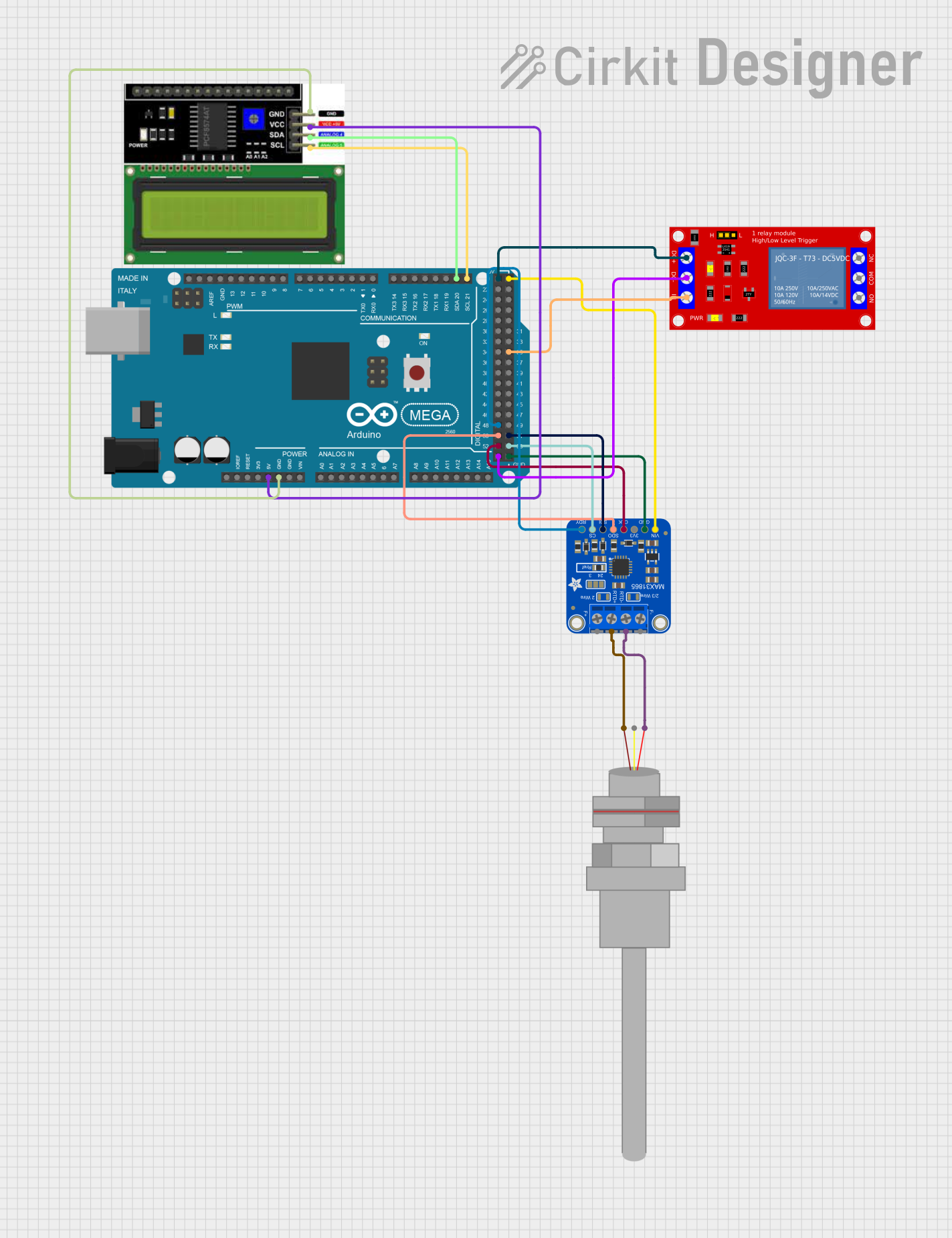
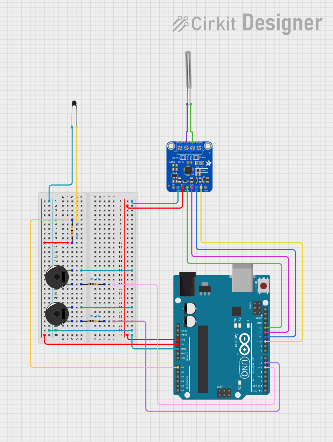
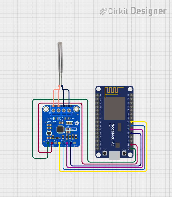
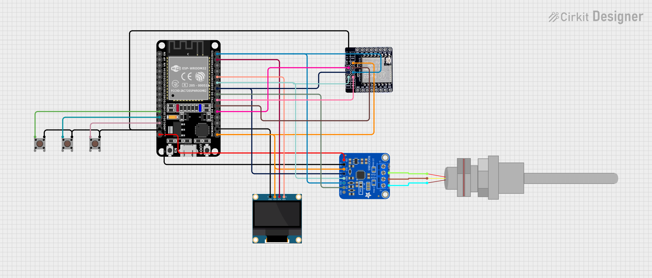
  2. Connecting to an Arduino UNO:

    • Use an RTD-to-analog converter module (e.g., MAX31865) to interface the PT100 with the Arduino.
    • Connect the RTD leads to the corresponding terminals on the converter module.
    • Connect the converter module to the Arduino UNO as follows:
      • VCC to 5V
      • GND to GND
      • SCK to Digital Pin 13
      • SDI to Digital Pin 11
      • SDO to Digital Pin 12
      • CS to Digital Pin 10

Important Considerations and Best Practices

  • Calibration: Ensure the RTD PT100 is calibrated for accurate temperature readings.
  • Lead Wire Resistance: Use a 3-wire configuration to minimize errors due to lead wire resistance.
  • Shielding: Shield the RTD wires to prevent electrical noise interference.
  • Temperature Range: Operate the RTD within its specified temperature range to avoid damage.

Sample Arduino Code

#include <SPI.h>
#include <Adafruit_MAX31865.h>

// Use software SPI: CS, DI, DO, CLK
Adafruit_MAX31865 max = Adafruit_MAX31865(10, 11, 12, 13);

// The value of the Rref resistor. Use 430.0 for PT100
#define RREF 430.0

void setup() {
  Serial.begin(9600);
  Serial.println("Adafruit MAX31865 PT100 Sensor Test!");

  max.begin(MAX31865_3WIRE);  // Initialize sensor for 3-wire RTD
}

void loop() {
  uint16_t rtd = max.readRTD();

  Serial.print("RTD value: "); Serial.println(rtd);
  float ratio = rtd;
  ratio /= 32768;
  Serial.print("Ratio = "); Serial.println(ratio, 8);
  Serial.print("Resistance = "); Serial.println(RREF * ratio, 8);
  Serial.print("Temperature = "); Serial.println(max.temperature(100, RREF));

  delay(1000);
}

Troubleshooting and FAQs

Common Issues and Solutions

  1. Inaccurate Temperature Readings:

    • Solution: Ensure proper calibration and use a 3-wire configuration to compensate for lead resistance.
  2. No Temperature Reading:

    • Solution: Check all connections and ensure the RTD and converter module are properly connected to the Arduino.
  3. Fluctuating Readings:

    • Solution: Shield the RTD wires to reduce electrical noise and ensure stable power supply.

FAQs

Q: Can I use a 2-wire configuration for the RTD PT100? A: Yes, but it may introduce errors due to lead wire resistance. A 3-wire configuration is recommended for higher accuracy.

Q: What is the maximum temperature the RTD PT100 can measure? A: The RTD PT100 can measure temperatures up to 850°C, but ensure it is within the specified range for your specific RTD class.

Q: How do I calibrate the RTD PT100? A: Calibration can be done using a known temperature reference and adjusting the measurement system to match the reference.

This documentation provides a comprehensive guide to using the RTD PT100 for precise temperature measurements. Whether you are a beginner or an experienced user, following these instructions and best practices will help you achieve accurate and reliable results.