How to Use ACS758: Examples, Pinouts, and Specs
Introduction
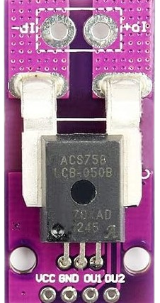
The ACS758 is a Hall-effect current sensor designed for accurate and reliable current measurement in both AC and DC applications. It provides galvanic isolation, making it ideal for use in systems where electrical isolation is critical. The sensor outputs an analog voltage proportional to the current flowing through its primary conductor, enabling real-time monitoring of current in various applications.
Explore Projects Built with ACS758


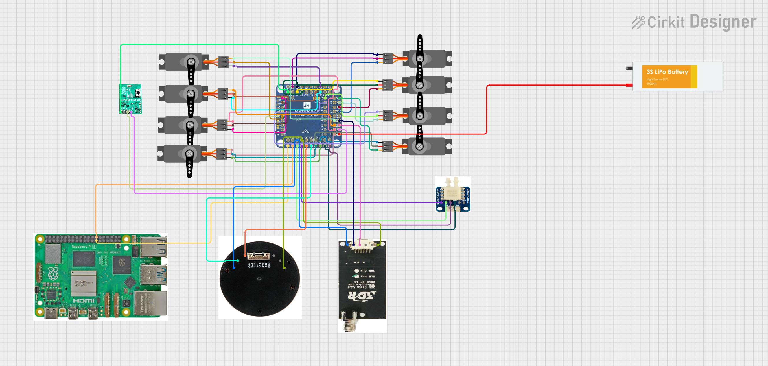
Explore Projects Built with ACS758
Common Applications
- Power monitoring in industrial and consumer electronics
- Battery management systems (BMS)
- Motor control and protection
- Solar inverters and renewable energy systems
- Overcurrent protection in power supplies
Technical Specifications
The ACS758 is available in multiple variants to support different current ranges. Below are the key technical details:
| Parameter | Value |
|---|---|
| Supply Voltage (Vcc) | 3.0V to 5.5V |
| Current Measurement Range | ±50A, ±100A, ±150A, ±200A (depending on model) |
| Sensitivity | 20mV/A to 40mV/A (model-dependent) |
| Output Voltage Range | 0.5V to 4.5V (nominal) |
| Isolation Voltage | 3.0kV RMS |
| Response Time | 4 µs |
| Operating Temperature Range | -40°C to +150°C |
Pin Configuration and Descriptions
The ACS758 is typically available in a 5-pin package. Below is the pinout description:
| Pin Number | Pin Name | Description |
|---|---|---|
| 1 | Vcc | Power supply input (3.0V to 5.5V) |
| 2 | GND | Ground |
| 3 | VIOUT | Analog output voltage proportional to current |
| 4 | IP+ | Positive current input terminal |
| 5 | IP- | Negative current input terminal |
Usage Instructions
How to Use the ACS758 in a Circuit
- Power Supply: Connect the Vcc pin to a stable 3.3V or 5V power supply and the GND pin to the ground of the circuit.
- Current Path: Pass the current to be measured through the IP+ and IP- terminals. Ensure the current does not exceed the rated range of the specific ACS758 variant.
- Output Signal: The VIOUT pin provides an analog voltage proportional to the current. This output can be read using an ADC (Analog-to-Digital Converter) on a microcontroller or other measurement devices.
- Filtering: For improved signal stability, connect a decoupling capacitor (e.g., 1 µF) between Vcc and GND.
Important Considerations
- Current Direction: The sensor outputs a voltage centered around 2.5V (for a 5V supply). Positive currents increase the output voltage, while negative currents decrease it.
- Isolation: Ensure proper isolation between the high-current path and the low-voltage control circuitry.
- Accuracy: Minimize external magnetic fields near the sensor to avoid interference.
- Thermal Management: The ACS758 can handle high currents, but excessive heat may affect accuracy. Ensure adequate cooling if necessary.
Example: Connecting ACS758 to an Arduino UNO
Below is an example of how to interface the ACS758 with an Arduino UNO to measure current:
// Example code to read current using ACS758 and Arduino UNO
const int sensorPin = A0; // Connect VIOUT of ACS758 to Arduino A0
const float sensitivity = 0.04; // Sensitivity in V/A (e.g., 40mV/A for ±50A model)
const float offsetVoltage = 2.5; // Output voltage at 0A (for 5V supply)

void setup() {
  Serial.begin(9600); // Initialize serial communication
  pinMode(sensorPin, INPUT); // Set sensor pin as input
}

void loop() {
  int sensorValue = analogRead(sensorPin); // Read ADC value (0-1023)
  float voltage = (sensorValue / 1023.0) * 5.0; // Convert ADC value to voltage
  float current = (voltage - offsetVoltage) / sensitivity;
  // Calculate current based on sensitivity and offset

  Serial.print("Current: ");
  Serial.print(current, 2); // Print current with 2 decimal places
  Serial.println(" A"); // Append unit (Amperes)

  delay(500); // Wait for 500ms before next reading
}
Notes:
- Adjust the
sensitivityandoffsetVoltagevalues based on the specific ACS758 variant and supply voltage. - Use a stable power supply for accurate readings.
Troubleshooting and FAQs
Common Issues and Solutions
No Output or Incorrect Readings
- Cause: Incorrect wiring or loose connections.
- Solution: Double-check all connections, especially Vcc, GND, and VIOUT.
Fluctuating Output Voltage
- Cause: Noise or insufficient decoupling.
- Solution: Add a decoupling capacitor (e.g., 1 µF) between Vcc and GND.
Output Voltage Does Not Change with Current
- Cause: Current is outside the measurable range or sensor is damaged.
- Solution: Verify the current range and ensure it matches the sensor's specifications.
High Offset Voltage
- Cause: External magnetic interference or improper calibration.
- Solution: Shield the sensor from external magnetic fields and recalibrate if necessary.
FAQs
Q: Can the ACS758 measure both AC and DC currents?
A: Yes, the ACS758 can measure both AC and DC currents with high accuracy.
Q: How do I select the correct ACS758 variant?
A: Choose a variant based on the maximum current you need to measure. For example, use the ±50A model for currents up to 50A.
Q: What is the typical accuracy of the ACS758?
A: The typical accuracy is ±1% of the full-scale current, depending on the variant and operating conditions.
Q: Can I use the ACS758 with a 3.3V microcontroller?
A: Yes, the ACS758 operates with a supply voltage as low as 3.0V, making it compatible with 3.3V systems.
Q: Is the ACS758 suitable for high-frequency current measurement?
A: The ACS758 has a response time of 4 µs, making it suitable for most applications, but it may not be ideal for very high-frequency signals.
By following this documentation, you can effectively integrate the ACS758 into your projects for accurate current measurement.