How to Use Módem de datos de Radio RFD900X, 900MHz,: Examples, Pinouts, and Specs
Introduction
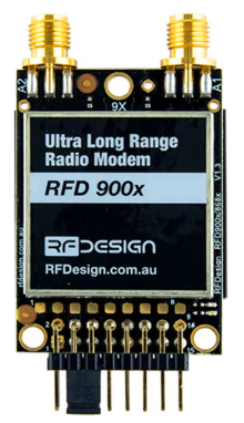
The RFD900X is a long-range, low-power radio modem operating at 900MHz, designed for reliable data transmission in remote applications. It is widely used in telemetry, remote control, and wireless communication tasks where robust and efficient data transfer is critical. The modem supports various data rates and incorporates advanced error correction mechanisms, ensuring reliable performance even in challenging environments.
Explore Projects Built with Módem de datos de Radio RFD900X, 900MHz,


Explore Projects Built with Módem de datos de Radio RFD900X, 900MHz,
Common Applications
- Telemetry for drones, UAVs, and robotics
- Remote control systems
- Wireless sensor networks
- Industrial automation and monitoring
- Long-range data communication in rural or remote areas
Technical Specifications
Key Technical Details
| Parameter | Specification |
|---|---|
| Frequency Range | 902–928 MHz (ISM Band) |
| Transmit Power | Up to 1 Watt (30 dBm) |
| Receiver Sensitivity | -117 dBm |
| Data Rate | 500 bps to 250 kbps |
| Modulation | GFSK |
| Voltage Range | 3.3V to 5.5V |
| Current Consumption | 100 mA (typical) at 5V, 1W output |
| Communication Interface | UART (TTL level) |
| Dimensions | 30 mm x 57 mm x 12 mm |
| Operating Temperature | -40°C to +85°C |
| Antenna Connector | RP-SMA |
Pin Configuration and Descriptions
| Pin Number | Pin Name | Description |
|---|---|---|
| 1 | GND | Ground connection |
| 2 | VCC | Power supply input (3.3V to 5.5V) |
| 3 | TX | UART Transmit (data output from the modem) |
| 4 | RX | UART Receive (data input to the modem) |
| 5 | RTS | Request to Send (flow control, optional) |
| 6 | CTS | Clear to Send (flow control, optional) |
| 7 | CONFIG | Configuration mode pin (pull high to enter configuration mode) |
| 8 | AUX | Auxiliary status indicator (used for diagnostics and connection status) |
Usage Instructions
How to Use the RFD900X in a Circuit
- Power Supply: Connect the
VCCpin to a stable power source (3.3V to 5.5V) and theGNDpin to ground. - UART Communication: Connect the
TXpin of the RFD900X to theRXpin of your microcontroller, and theRXpin of the RFD900X to theTXpin of your microcontroller. - Antenna: Attach a compatible 900MHz antenna to the RP-SMA connector for optimal performance.
- Configuration: If needed, pull the
CONFIGpin high to enter configuration mode and adjust settings such as frequency, data rate, and power output using the provided configuration software. - Flow Control (Optional): Connect the
RTSandCTSpins if hardware flow control is required for your application.
Important Considerations and Best Practices
- Antenna Placement: Ensure the antenna is placed in an open area, away from obstructions and interference sources, to maximize range and signal quality.
- Power Supply: Use a low-noise, regulated power supply to avoid introducing noise into the communication system.
- Heat Dissipation: The modem may heat up during high-power transmission. Ensure adequate ventilation or heat sinking if used in continuous high-power applications.
- Configuration Software: Use the official RFD900X configuration tool to set parameters such as frequency, power output, and data rate. Always verify settings before deployment.
Example: Connecting to an Arduino UNO
Below is an example of how to connect and use the RFD900X with an Arduino UNO for basic communication.
Wiring Diagram
| RFD900X Pin | Arduino UNO Pin |
|---|---|
| VCC | 5V |
| GND | GND |
| TX | RX (Pin 0) |
| RX | TX (Pin 1) |
Arduino Code Example
// Example code for using the RFD900X with Arduino UNO
// This code sends a message via the RFD900X and listens for a response.

void setup() {
  Serial.begin(9600); // Initialize UART communication at 9600 baud
  delay(1000);        // Allow the modem to initialize
  Serial.println("RFD900X Test Message"); // Send a test message
}

void loop() {
  if (Serial.available()) { // Check if data is received from the modem
    String receivedData = Serial.readString(); // Read the incoming data
    Serial.println("Received: " + receivedData); // Print the received data
  }
}
Notes:
- Ensure the baud rate in the code matches the modem's configured baud rate.
- Avoid using the Arduino's hardware serial pins (0 and 1) for other purposes when using the RFD900X.
Troubleshooting and FAQs
Common Issues and Solutions
No Communication Between Devices
- Verify the
TXandRXconnections are correctly wired. - Ensure the baud rate of the modem matches the microcontroller's UART settings.
- Check the power supply voltage and current to ensure the modem is powered correctly.
- Verify the
Poor Signal Quality or Range
- Ensure the antenna is securely connected and properly positioned.
- Avoid placing the modem near metal objects or other sources of interference.
- Increase the transmit power using the configuration software if necessary.
Modem Not Entering Configuration Mode
- Ensure the
CONFIGpin is pulled high before powering on the modem. - Verify the configuration software is compatible with the RFD900X.
- Ensure the
Overheating
- Reduce the transmit power if continuous high-power operation is not required.
- Provide adequate ventilation or a heat sink to dissipate heat.
FAQs
Q: Can the RFD900X be used with 3.3V microcontrollers?
A: Yes, the RFD900X is compatible with both 3.3V and 5V systems, making it suitable for a wide range of microcontrollers.
Q: What is the maximum range of the RFD900X?
A: The maximum range depends on the environment and antenna used. In open areas with line-of-sight, it can achieve ranges of up to 40 km.
Q: How do I update the firmware on the RFD900X?
A: Firmware updates can be performed using the official configuration tool and a USB-to-UART adapter. Follow the manufacturer's instructions for the update process.
Q: Is the RFD900X compatible with other 900MHz modems?
A: Yes, the RFD900X can communicate with other 900MHz modems that use the same protocol and settings. Ensure both devices are configured with matching parameters.