
How to Use HY-103: Examples, Pinouts, and Specs
 Design with HY-103 in Cirkit Designer
Introduction
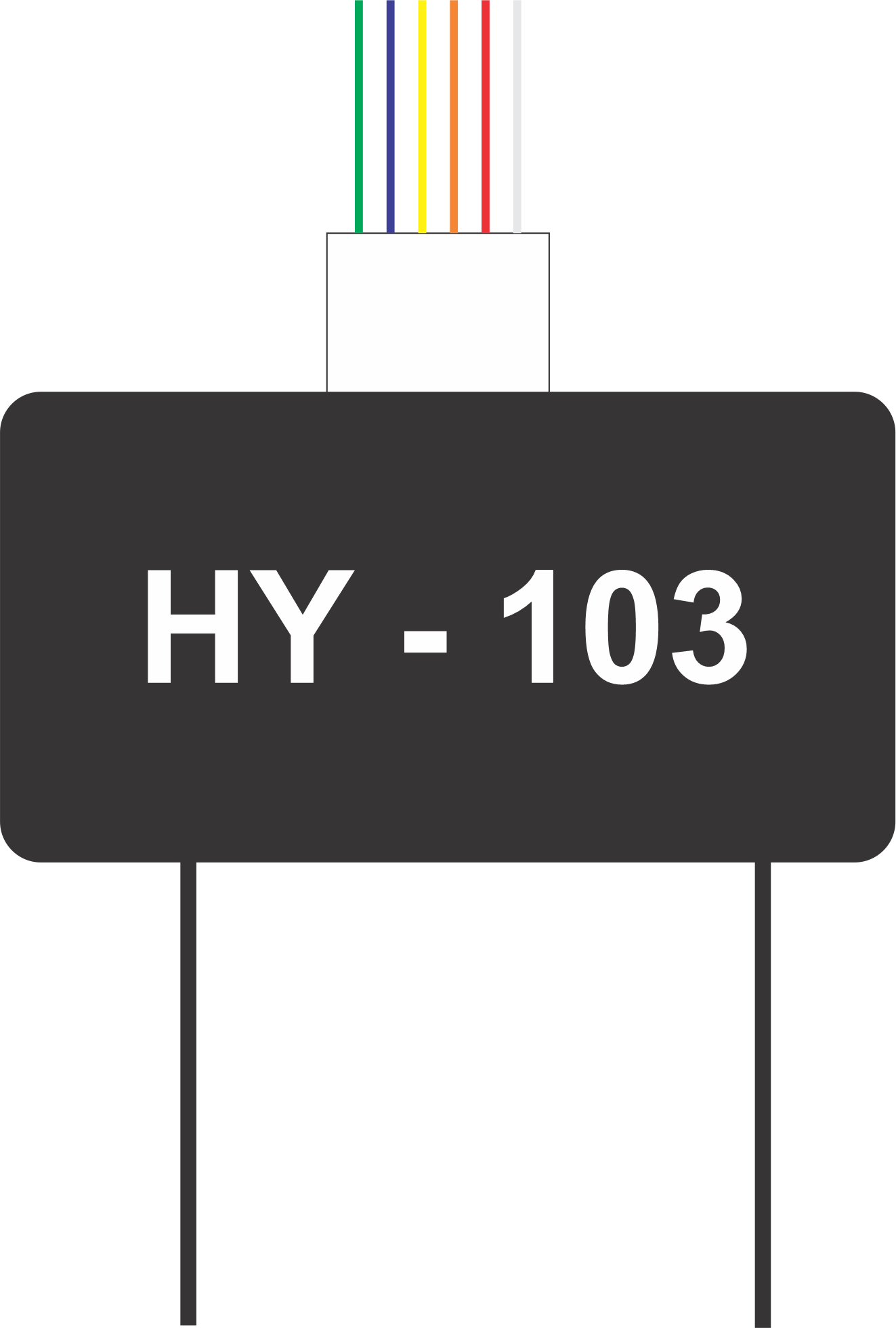
The HY-103, manufactured by BATARA, is a compact, low-cost, high-performance DC-DC buck converter module. It is designed to efficiently step down higher input voltages to lower output voltages, making it ideal for a wide range of electronic applications. Its small size and high efficiency make it a popular choice for powering microcontrollers, sensors, and other low-voltage devices in embedded systems.
Explore Projects Built with HY-103
 Open Project in Cirkit Designer
 Open Project in Cirkit Designer
 Open Project in Cirkit Designer
 Open Project in Cirkit Designer
Explore Projects Built with HY-103
Open Project in Cirkit DesignerOpen Project in Cirkit DesignerOpen Project in Cirkit DesignerOpen Project in Cirkit DesignerCommon Applications and Use Cases
- Powering microcontrollers (e.g., Arduino, Raspberry Pi)
- Voltage regulation in battery-powered devices
- Supplying power to sensors and modules in IoT systems
- General-purpose voltage step-down in electronic circuits
Technical Specifications
The HY-103 offers robust performance and flexibility for various voltage regulation needs. Below are its key technical specifications:
| Parameter | Value |
|---|---|
| Input Voltage Range | 4.5V to 28V |
| Output Voltage Range | 0.8V to 20V (adjustable) |
| Maximum Output Current | 3A |
| Efficiency | Up to 92% |
| Switching Frequency | 150 kHz |
| Operating Temperature | -40°C to +85°C |
| Dimensions | 22mm x 17mm x 4mm |
Pin Configuration and Descriptions
The HY-103 module has four pins for easy integration into circuits. The table below describes each pin:
| Pin Name | Description |
|---|---|
| VIN | Input voltage pin. Connect to the positive terminal of the input power source. |
| GND | Ground pin. Connect to the negative terminal of the input power source. |
| VOUT | Output voltage pin. Provides the regulated output voltage. |
| ADJ | Adjustment pin. Used to set the output voltage via an external potentiometer. |
Usage Instructions
The HY-103 is straightforward to use in a circuit. Follow the steps below to integrate it into your design:
Connect the Input Voltage:
- Connect the VIN pin to the positive terminal of your power source.
- Connect the GND pin to the negative terminal of your power source.
Set the Output Voltage:
- Use the ADJ pin to adjust the output voltage. Typically, this is done by connecting a potentiometer or resistor divider to the ADJ pin.
- Measure the output voltage at the VOUT pin using a multimeter and adjust the potentiometer until the desired voltage is achieved.
Connect the Load:
- Connect the device or circuit you want to power to the VOUT pin and GND pin.
Verify Connections:
- Double-check all connections to ensure proper polarity and secure wiring.
Important Considerations and Best Practices
- Input Voltage Range: Ensure the input voltage is within the specified range (4.5V to 28V). Exceeding this range may damage the module.
- Heat Dissipation: For high-current applications, consider adding a heatsink or improving airflow around the module to prevent overheating.
- Output Voltage Adjustment: Use a precise multimeter when adjusting the output voltage to avoid overvoltage or undervoltage conditions.
- Capacitors: Add input and output capacitors (e.g., 10µF to 100µF) close to the module to improve stability and reduce noise.
Example: Using HY-103 with Arduino UNO
The HY-103 can be used to power an Arduino UNO by stepping down a 12V input to 5V. Below is an example circuit and Arduino code:
Circuit Connections:
- Connect a 12V power source to the VIN and GND pins of the HY-103.
- Adjust the output voltage to 5V using the ADJ pin.
- Connect the VOUT pin of the HY-103 to the 5V pin of the Arduino UNO.
- Connect the GND pin of the HY-103 to the GND pin of the Arduino UNO.
Arduino Code:
// Example code to blink an LED connected to pin 13 of the Arduino UNO
// Ensure the HY-103 is providing a stable 5V to the Arduino UNO.

void setup() {
  pinMode(13, OUTPUT); // Set pin 13 as an output pin
}

void loop() {
  digitalWrite(13, HIGH); // Turn the LED on
  delay(1000);            // Wait for 1 second
  digitalWrite(13, LOW);  // Turn the LED off
  delay(1000);            // Wait for 1 second
}
Troubleshooting and FAQs
Common Issues and Solutions
No Output Voltage:
- Cause: Incorrect wiring or insufficient input voltage.
- Solution: Verify that the VIN and GND pins are connected correctly and that the input voltage is within the specified range.
Output Voltage Fluctuates:
- Cause: Insufficient input/output capacitors or unstable input power source.
- Solution: Add capacitors (e.g., 10µF to 100µF) close to the VIN and VOUT pins to stabilize the voltage.
Module Overheats:
- Cause: Excessive current draw or poor heat dissipation.
- Solution: Ensure the load does not exceed the 3A maximum current rating. Add a heatsink or improve airflow around the module.
Cannot Adjust Output Voltage:
- Cause: Faulty potentiometer or incorrect adjustment procedure.
- Solution: Replace the potentiometer and ensure proper adjustment using a multimeter.
FAQs
Q: Can the HY-103 be used with a 24V input?
A: Yes, the HY-103 supports input voltages up to 28V. Ensure the output voltage is adjusted appropriately for your application.
Q: What is the minimum load current required for stable operation?
A: The HY-103 does not require a minimum load current for stable operation, but adding a small load (e.g., 10mA) can improve performance in some cases.
Q: Is the HY-103 protected against short circuits?
A: No, the HY-103 does not have built-in short-circuit protection. Use external protection circuits if needed.
Q: Can I use the HY-103 to power a Raspberry Pi?
A: Yes, the HY-103 can be used to power a Raspberry Pi. Ensure the output voltage is set to 5V and the current requirement does not exceed 3A.