How to Use ESP8266-01 Relay: Examples, Pinouts, and Specs
Introduction
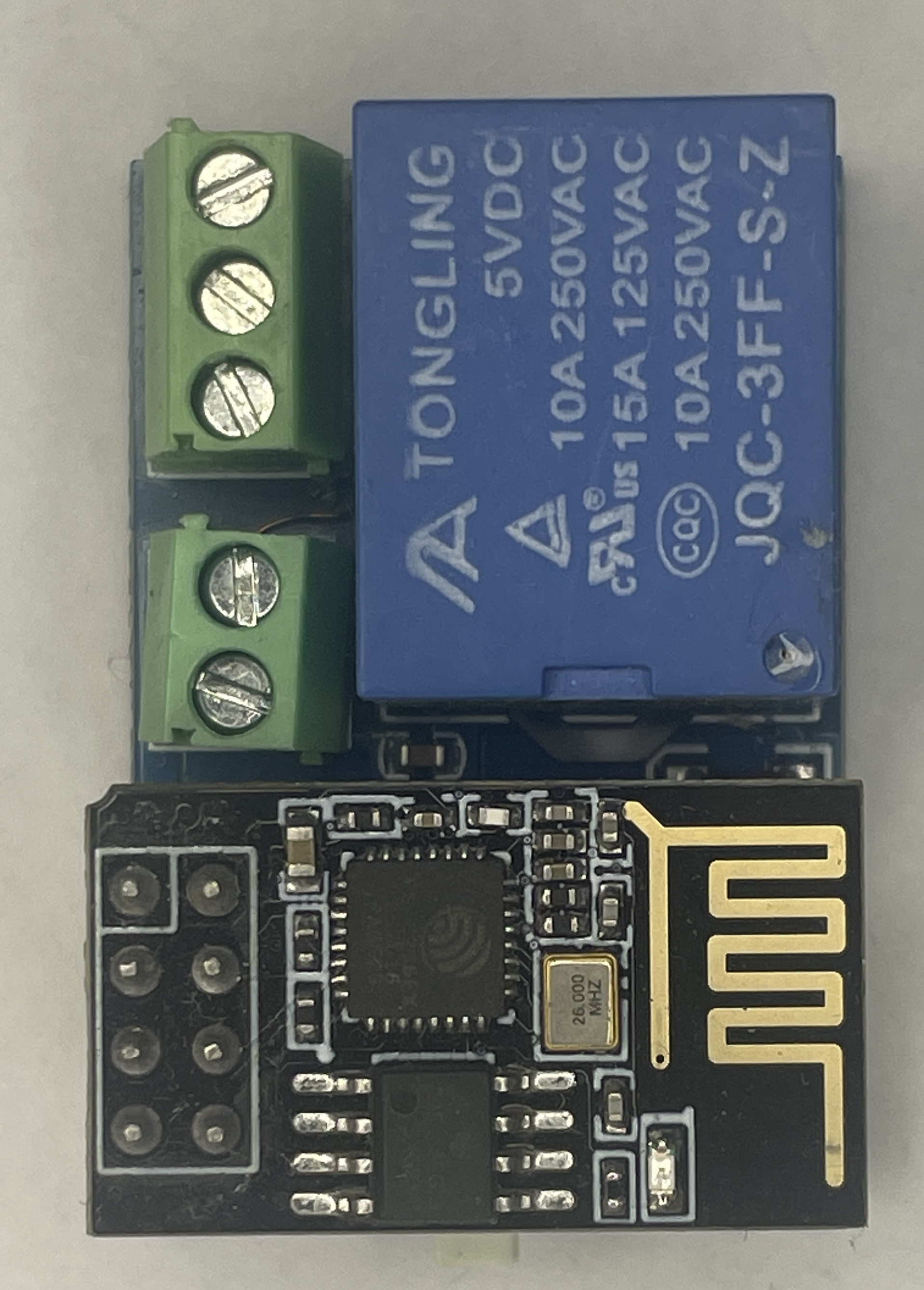
The ESP8266-01 Relay module is a compact and versatile component that integrates the popular ESP8266 WiFi module with a single relay, enabling wireless control of various appliances and systems. This module is widely used in the realm of Internet of Things (IoT) for home automation, remote switching, and other applications where wireless control is desired.
Explore Projects Built with ESP8266-01 Relay


Explore Projects Built with ESP8266-01 Relay
Common Applications and Use Cases
- Home automation systems
- Remote control for lights, fans, and other household appliances
- IoT projects for controlling power to devices over the internet
- DIY smart home devices
Technical Specifications
Key Technical Details
- Operating Voltage: 5V DC
- WiFi Standard: 802.11 b/g/n
- Relay Rating: 10A 250V AC / 10A 30V DC
- Operating Modes: Station / Access Point (AP)
- Serial Communication: UART, 115200 bps by default
Pin Configuration and Descriptions
| Pin Number | Pin Name | Description |
|---|---|---|
| 1 | VCC | 5V Power Supply Input |
| 2 | GND | Ground |
| 3 | TX | Transmit Pin (connect to RX of MCU) |
| 4 | RX | Receive Pin (connect to TX of MCU) |
| 5 | GPIO0 | General Purpose I/O (used for modes) |
| 6 | GPIO2 | General Purpose I/O (not used) |
| 7 | Relay | Relay control signal (active high) |
| 8 | RST | Reset Pin |
Usage Instructions
How to Use the Component in a Circuit
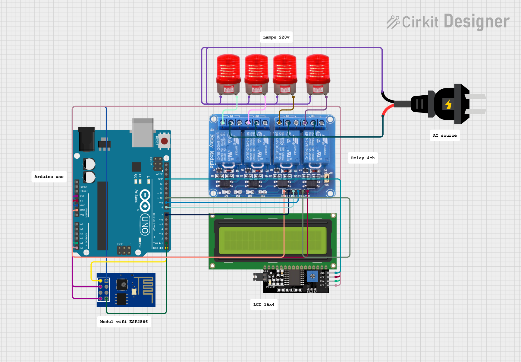
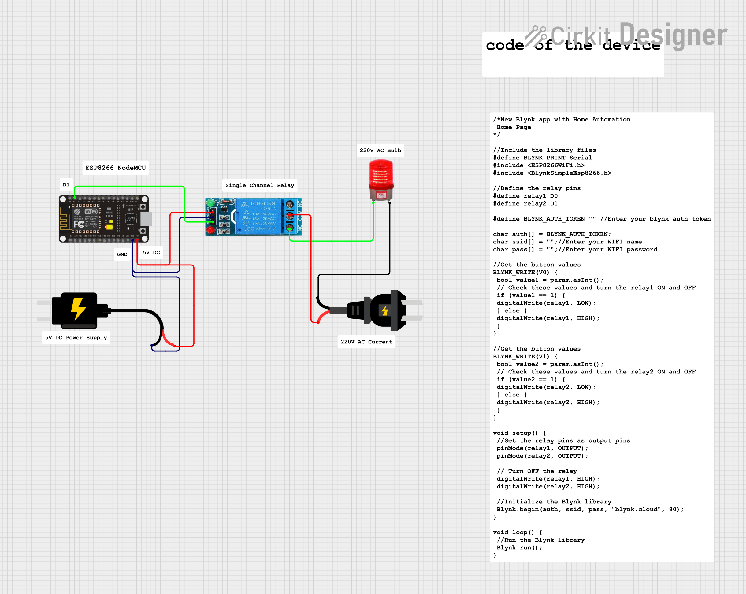
- Connect the VCC pin to a 5V power supply.
- Connect the GND pin to the ground of the power supply.
- Interface the TX and RX pins with a microcontroller such as an Arduino UNO for serial communication.
- The GPIO0 pin can be used to set the module in programming mode or normal operation mode.
- The Relay pin is used to control the relay. Apply a high signal to turn the relay on, and a low signal to turn it off.
- The RST pin can be used to reset the module.
Important Considerations and Best Practices
- Ensure that the power supply is capable of providing sufficient current for both the ESP8266 module and the relay coil.
- Be cautious when working with mains voltage. If the relay is used to switch high voltages, appropriate safety measures should be taken.
- Use a flyback diode across the relay coil if driving inductive loads to prevent back EMF damage.
- Avoid placing the module in areas with high electromagnetic interference to prevent WiFi communication issues.
Example Code for Arduino UNO
#include <ESP8266WiFi.h>

// Replace with your network credentials
const char* ssid = "yourSSID";
const char* password = "yourPASSWORD";

WiFiServer server(80);

void setup() {
  Serial.begin(115200);
  pinMode(0, OUTPUT); // Relay pin set as output
  digitalWrite(0, LOW); // Start with the relay off

  // Connect to Wi-Fi
  WiFi.begin(ssid, password);
  while (WiFi.status() != WL_CONNECTED) {
    delay(500);
    Serial.print(".");
  }

  server.begin();
}

void loop() {
  WiFiClient client = server.available(); // Listen for incoming clients

  if (client) { // If a new client connects,
    String currentLine = ""; // make a String to hold incoming data from the client
    while (client.connected()) { // loop while the client's connected
      if (client.available()) { // if there's bytes to read from the client,
        char c = client.read(); // read a byte, then
        Serial.write(c); // print it out the serial monitor
        if (c == '\n') { // if the byte is a newline character

          // if the current line is blank, you got two newline characters in a row.
          // that's the end of the client HTTP request, so send a response:
          if (currentLine.length() == 0) {
            // HTTP headers always start with a response code (e.g. HTTP/1.1 200 OK)
            // and a content-type so the client knows what's coming, then a blank line:
            client.println("HTTP/1.1 200 OK");
            client.println("Content-type:text/html");
            client.println();

            // turns the GPIO0 on and off
            if (client.read() == '1') {
              digitalWrite(0, HIGH); // Turn the relay on
            } else {
              digitalWrite(0, LOW); // Turn the relay off
            }

            // The HTTP response ends with another blank line:
            client.println();
            break;
          } else { // if you got a newline, then clear currentLine:
            currentLine = "";
          }
        } else if (c != '\r') { // if you got anything else but a carriage return character,
          currentLine += c; // add it to the end of the currentLine
        }
      }
    }
    // Clear the client's request and close the connection:
    client.stop();
    Serial.println("Client Disconnected.");
  }
}
Troubleshooting and FAQs
Common Issues Users Might Face
- WiFi Connectivity Problems: Ensure the module is within range of the WiFi router and that the SSID and password are correctly entered in the code.
- Relay Not Activating: Check the connections to the relay pin and ensure that the power supply is adequate.
- Module Not Responding: Verify that the module is correctly powered and that the serial communication is properly established with the microcontroller.
Solutions and Tips for Troubleshooting
- Power Issues: Use a separate power supply for the relay if the ESP8266 is resetting due to power drops when the relay activates.
- Interference: Keep the module away from large metal objects and devices that can cause electromagnetic interference.
- Firmware Issues: If the module is not functioning correctly, consider reflashing the firmware.
FAQs
Q: Can the ESP8266-01 Relay module be used with batteries? A: Yes, but ensure the batteries can provide a stable 5V output and can handle the current draw of the module and relay.
Q: How many devices can I control with the ESP8266-01 Relay module? A: The module has one relay, so it can control one device at a time. However, multiple modules can be used in parallel to control more devices.
Q: Is it possible to control the relay over the internet? A: Yes, with the appropriate network configuration and programming, the relay can be controlled over the internet.