How to Use GPS module: Examples, Pinouts, and Specs
Introduction
A GPS module is a device that receives signals from satellites to determine the precise location (latitude, longitude, and altitude) of the device. It is commonly used in navigation systems, tracking applications, and various electronic devices to provide location-based services. GPS modules are essential in applications such as vehicle tracking, geofencing, outdoor navigation, and IoT devices requiring location data.
Explore Projects Built with GPS module
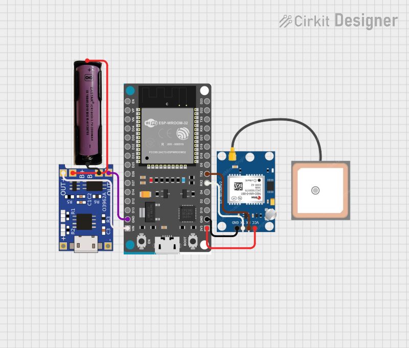


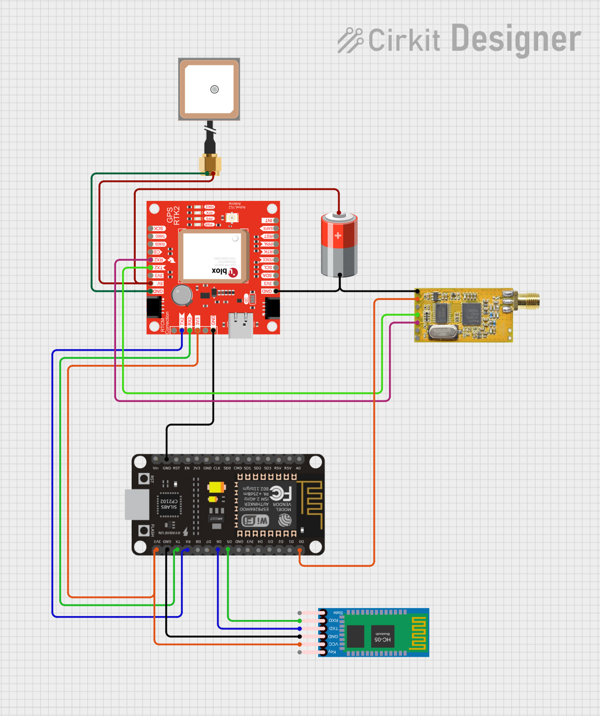
Explore Projects Built with GPS module
Technical Specifications
Below are the key technical details of a typical GPS module:
- Input Voltage: 3.3V to 5V (varies by model)
- Communication Protocol: UART (Universal Asynchronous Receiver-Transmitter)
- Baud Rate: 9600 bps (default, configurable)
- Position Accuracy: Typically ±2.5 meters
- Update Rate: 1 Hz to 10 Hz (depending on the module)
- Antenna: Built-in or external (active or passive)
- Operating Temperature: -40°C to +85°C
- Power Consumption: ~20 mA to 50 mA (varies by model)
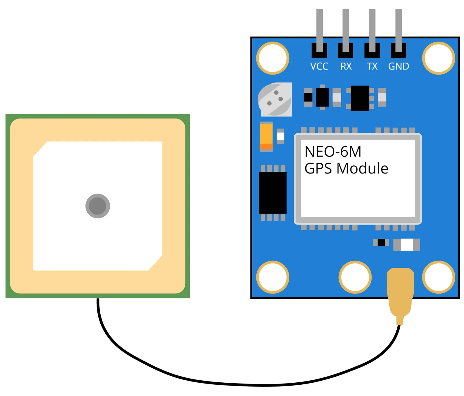
Pin Configuration and Descriptions
The pinout of a GPS module may vary slightly depending on the manufacturer, but the following table describes the typical pin configuration:
| Pin Name | Description |
|---|---|
| VCC | Power supply input (3.3V or 5V, depending on the module). |
| GND | Ground connection. |
| TX | Transmit pin (sends data from the GPS module to the microcontroller). |
| RX | Receive pin (receives data from the microcontroller, if applicable). |
| PPS | Pulse per second output (optional, provides a precise timing signal). |
| EN (Enable) | Optional pin to enable or disable the module (active high). |
Usage Instructions
How to Use the GPS Module in a Circuit
- Power the Module: Connect the VCC pin to a 3.3V or 5V power source (as specified by the module) and the GND pin to the ground.
- Connect to a Microcontroller:
- Connect the TX pin of the GPS module to the RX pin of the microcontroller.
- Connect the RX pin of the GPS module to the TX pin of the microcontroller (if bidirectional communication is required).
- Antenna Placement: Ensure the GPS module has a clear view of the sky for optimal satellite signal reception. If using an external antenna, connect it securely to the module.
- Configure the Module: Use the default baud rate (9600 bps) or configure it as needed using AT commands or software tools.
- Read Data: The module outputs NMEA sentences (e.g., GPGGA, GPRMC) containing location, time, and other data. Parse these sentences in your microcontroller or software.
Important Considerations and Best Practices
- Power Supply: Ensure a stable and clean power supply to avoid interference with GPS signal reception.
- Antenna Orientation: Place the antenna in an open area, away from obstructions like buildings or metal objects.
- Signal Acquisition: The first GPS fix may take longer (cold start). Subsequent fixes (warm start) are faster.
- Data Parsing: Use libraries or software tools to parse NMEA sentences efficiently.
- Interference: Avoid placing the GPS module near high-frequency components or RF transmitters.
Example: Connecting a GPS Module to an Arduino UNO
Below is an example of how to connect and use a GPS module with an Arduino UNO:
Circuit Connections
- GPS Module VCC → Arduino 5V
- GPS Module GND → Arduino GND
- GPS Module TX → Arduino Digital Pin 4 (SoftwareSerial RX)
- GPS Module RX → Arduino Digital Pin 3 (SoftwareSerial TX)
Arduino Code
#include <SoftwareSerial.h>

// Define RX and TX pins for SoftwareSerial
SoftwareSerial gpsSerial(4, 3); // RX = Pin 4, TX = Pin 3

void setup() {
  Serial.begin(9600); // Initialize Serial Monitor at 9600 bps
  gpsSerial.begin(9600); // Initialize GPS module at 9600 bps
  Serial.println("GPS Module Test");
}

void loop() {
  // Check if data is available from the GPS module
  while (gpsSerial.available()) {
    char c = gpsSerial.read(); // Read one character from GPS module
    Serial.print(c); // Print the character to the Serial Monitor
  }
}
Notes:
- Install the
TinyGPS++library for advanced parsing of GPS data. - Ensure the baud rate in the code matches the GPS module's default baud rate.
Troubleshooting and FAQs
Common Issues and Solutions
No Data Output from the GPS Module
- Solution: Verify the connections (TX and RX pins). Ensure the baud rate in the code matches the module's default baud rate.
GPS Module Fails to Acquire a Fix
- Solution: Place the module in an open area with a clear view of the sky. Check the antenna connection.
Intermittent or Unstable Data
- Solution: Use a stable power supply and avoid placing the module near sources of electromagnetic interference.
Incorrect or Incomplete NMEA Sentences
- Solution: Ensure the microcontroller's UART buffer is large enough to handle the incoming data.
FAQs
Q: Can I use the GPS module indoors?
- A: GPS modules work best outdoors. Indoors, signal reception may be weak or unavailable.
Q: How do I increase the update rate of the GPS module?
- A: Use AT commands or configuration software provided by the manufacturer to adjust the update rate.
Q: What is the purpose of the PPS pin?
- A: The PPS (Pulse Per Second) pin provides a precise timing signal, useful for time synchronization in certain applications.
Q: Can I use the GPS module with a 3.3V microcontroller?
- A: Yes, but ensure the module supports 3.3V logic levels or use a level shifter for compatibility.
This documentation provides a comprehensive guide to understanding, using, and troubleshooting a GPS module.