How to Use Sk120 36V 6A 120W Buck Converter CC CV Step Down Module LCD Adjustable Constant Voltage Power Supply: Examples, Pinouts, and Specs
Introduction
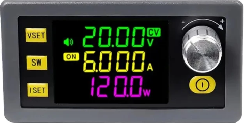
The SK120 is a high-performance DC-DC buck converter module designed to step down input voltage to a lower, adjustable output voltage. It supports both constant voltage (CV) and constant current (CC) modes, making it versatile for a wide range of applications. The module features an integrated LCD display for real-time monitoring of output voltage, current, and power, ensuring precise control and ease of use.
Explore Projects Built with Sk120 36V 6A 120W Buck Converter CC CV Step Down Module LCD Adjustable Constant Voltage Power Supply


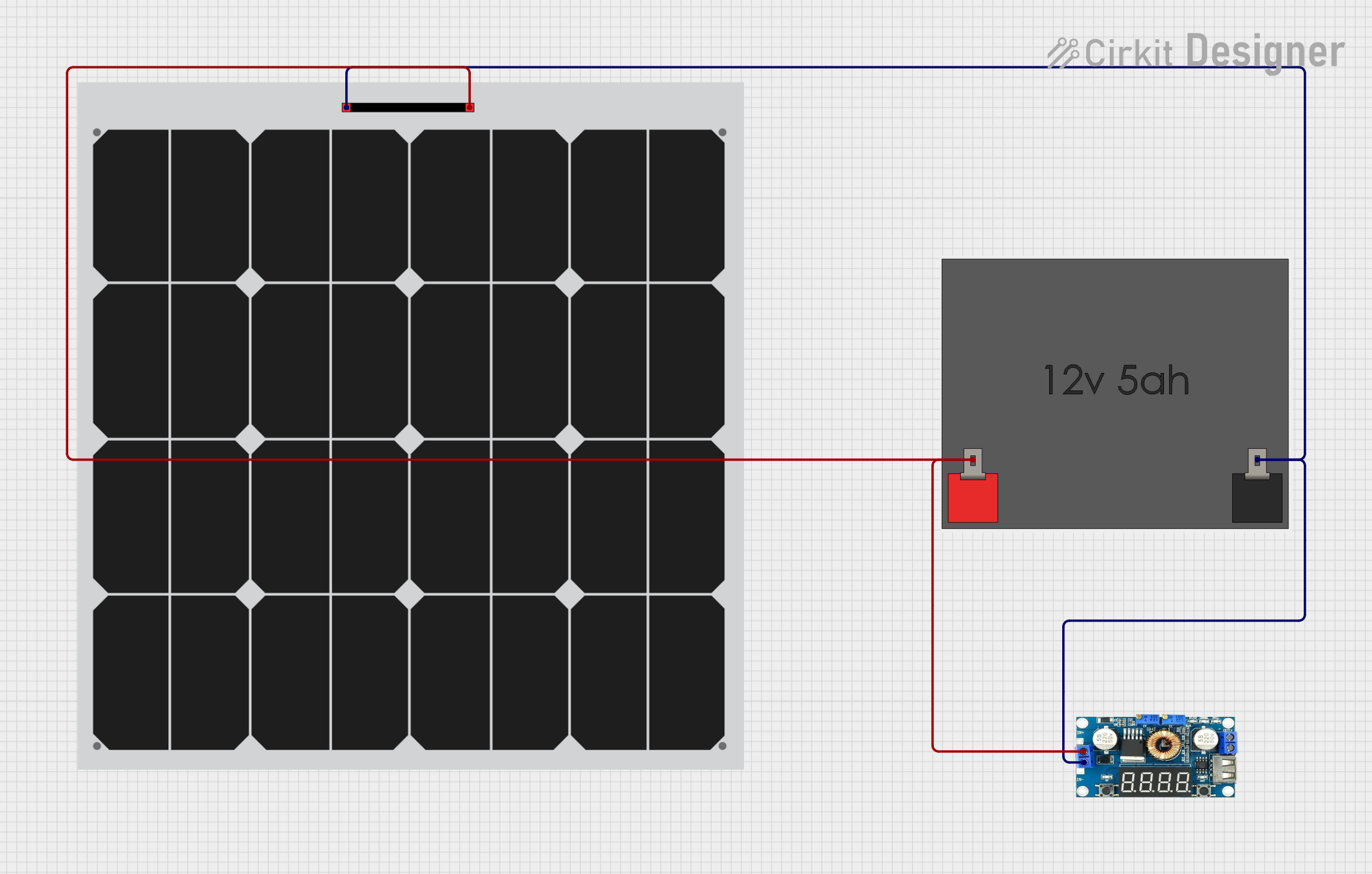
Explore Projects Built with Sk120 36V 6A 120W Buck Converter CC CV Step Down Module LCD Adjustable Constant Voltage Power Supply
Common Applications and Use Cases
- DIY adjustable power supplies
- Battery charging applications
- LED driver circuits
- Testing and powering electronic devices
- Laboratory and prototyping environments
Technical Specifications
The SK120 module is designed to handle high power and provide stable output. Below are its key technical specifications:
| Parameter | Value |
|---|---|
| Input Voltage Range | 6V to 40V |
| Output Voltage Range | 1.2V to 36V (adjustable) |
| Output Current | 0A to 6A (adjustable) |
| Output Power | Up to 120W |
| Efficiency | Up to 95% (depending on load) |
| Voltage Regulation | ±0.5% |
| Current Regulation | ±0.5% |
| Display | LCD (shows voltage, current, power) |
| Protection Features | Overcurrent, overvoltage, overtemperature, short circuit |
| Dimensions | 66mm x 48mm x 21mm |
Pin Configuration and Descriptions
The SK120 module has input and output terminals for easy integration into circuits. Below is the pin configuration:
| Pin Name | Description |
|---|---|
| VIN+ | Positive input voltage terminal (connect to the power source) |
| VIN- | Negative input voltage terminal (connect to the power source ground) |
| VOUT+ | Positive output voltage terminal (connect to the load) |
| VOUT- | Negative output voltage terminal (connect to the load ground) |
| Adjustment Knobs | Two potentiometers for adjusting output voltage (CV) and current (CC) |
Usage Instructions
How to Use the SK120 in a Circuit
Connect the Input Voltage:
- Connect the VIN+ and VIN- terminals to a DC power source within the input voltage range (6V to 40V).
- Ensure the input voltage is at least 1.5V higher than the desired output voltage for proper operation.
Connect the Load:
- Connect the VOUT+ and VOUT- terminals to the load (e.g., a device, battery, or circuit).
Adjust Output Voltage and Current:
- Use the voltage adjustment potentiometer to set the desired output voltage.
- Use the current adjustment potentiometer to set the maximum output current (useful for current-limiting applications).
Monitor Output Parameters:
- The LCD display will show real-time output voltage, current, and power. Use this information to verify the module's operation.
Switch Between CC and CV Modes:
- The module automatically switches between constant voltage (CV) and constant current (CC) modes based on the load requirements. The LCD will indicate the active mode.
Important Considerations and Best Practices
- Heat Dissipation: The module can generate heat during operation, especially at high currents. Ensure adequate ventilation or use a heatsink if necessary.
- Input Voltage: Do not exceed the maximum input voltage of 40V to avoid damaging the module.
- Output Power: Ensure the total output power does not exceed 120W to prevent overheating or failure.
- Polarity: Double-check the polarity of the input and output connections to avoid damage.
- Battery Charging: When using the module to charge batteries, set the output voltage and current according to the battery's specifications.
Example: Using the SK120 with an Arduino UNO
The SK120 can be used to power an Arduino UNO by stepping down a higher voltage (e.g., 12V) to 5V. Below is an example setup:
- Connect a 12V DC power source to the VIN+ and VIN- terminals of the SK120.
- Adjust the output voltage to 5V using the voltage adjustment potentiometer.
- Connect the VOUT+ and VOUT- terminals to the Arduino UNO's 5V and GND pins, respectively.
Here is a simple Arduino code example to test the setup with an LED:
// Simple LED blink example for Arduino UNO
// Ensure the SK120 is set to output 5V before connecting to the Arduino

const int ledPin = 13; // Built-in LED pin on Arduino UNO

void setup() {
  pinMode(ledPin, OUTPUT); // Set the LED pin as an output
}

void loop() {
  digitalWrite(ledPin, HIGH); // Turn the LED on
  delay(1000);                // Wait for 1 second
  digitalWrite(ledPin, LOW);  // Turn the LED off
  delay(1000);                // Wait for 1 second
}
Troubleshooting and FAQs
Common Issues and Solutions
No Output Voltage:
- Check the input voltage and ensure it is within the specified range.
- Verify the polarity of the input and output connections.
- Ensure the output voltage is not set to 0V using the adjustment potentiometer.
Overheating:
- Ensure the module is not exceeding its maximum power rating (120W).
- Provide adequate cooling or use a heatsink if operating at high currents.
LCD Display Not Working:
- Check the input voltage and ensure it is properly connected.
- Inspect the module for physical damage or loose connections.
Load Not Receiving Power:
- Verify the output voltage and current settings.
- Check for short circuits or incorrect wiring.
FAQs
Q: Can the SK120 charge lithium-ion batteries?
A: Yes, the SK120 can charge lithium-ion batteries. Set the output voltage to the battery's nominal voltage and the current to the recommended charging current.
Q: What happens if the input voltage exceeds 40V?
A: Exceeding 40V can damage the module. Always ensure the input voltage is within the specified range.
Q: Can I use the SK120 to power sensitive electronics?
A: Yes, the SK120 provides stable output voltage and current, making it suitable for sensitive electronics. However, verify the output settings before connecting your device.
Q: How do I know if the module is in CC or CV mode?
A: The LCD display will indicate the active mode. In CC mode, the current is limited to the set value, while in CV mode, the voltage is regulated to the set value.
By following this documentation, you can effectively use the SK120 module in your projects and troubleshoot common issues.