How to Use Step-Up Voltage Regulator: Examples, Pinouts, and Specs
Introduction
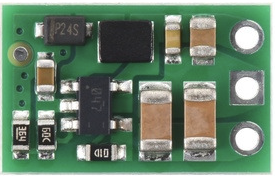
The Pololu U3V9F24 Step-Up Voltage Regulator is a compact and efficient device designed to increase a lower input voltage to a higher, regulated output voltage. This regulator is ideal for applications where a stable, higher voltage is required from a lower voltage power source, such as batteries or low-voltage power supplies. Its small size and high efficiency make it suitable for portable electronics, robotics, and embedded systems.
Explore Projects Built with Step-Up Voltage Regulator


Explore Projects Built with Step-Up Voltage Regulator
Common Applications
- Powering devices requiring a higher voltage from a battery (e.g., 3.7V LiPo to 12V).
- Boosting voltage for LED strips, sensors, or communication modules.
- Robotics and motor controllers.
- Portable electronics and DIY projects.
Technical Specifications
The following table outlines the key technical details of the Pololu U3V9F24 Step-Up Voltage Regulator:
| Parameter | Value |
|---|---|
| Input Voltage Range | 2.5V to 9V |
| Output Voltage | Fixed at 24V |
| Maximum Output Current | 500 mA (varies with input voltage; see datasheet for details) |
| Efficiency | Up to 85% (depending on input voltage and load) |
| Quiescent Current | <1 mA |
| Dimensions | 12.7 mm × 22.9 mm × 3.8 mm |
| Weight | 1.2 g |
| Operating Temperature | -40°C to +85°C |
| Protection Features | Over-temperature shutdown, short-circuit protection, reverse voltage protection |
Pin Configuration and Descriptions
The Pololu U3V9F24 has three main pins for connection:
| Pin Name | Description |
|---|---|
| VIN | Input voltage pin (2.5V to 9V). Connect to the positive terminal of the power source. |
| GND | Ground pin. Connect to the negative terminal of the power source. |
| VOUT | Regulated output voltage pin (24V). Connect to the load requiring 24V. |
Usage Instructions
How to Use the Component in a Circuit
- Power Source Connection: Connect the input voltage (VIN) pin to a power source within the range of 2.5V to 9V. Ensure the power source can supply sufficient current for your load.
- Ground Connection: Connect the GND pin to the ground of your circuit.
- Output Connection: Connect the VOUT pin to the device or circuit requiring a 24V supply.
- Bypass Capacitors: For optimal performance, it is recommended to add a capacitor (e.g., 10 µF) across the VIN and GND pins to stabilize the input voltage.
Important Considerations and Best Practices
- Input Voltage Range: Ensure the input voltage stays within the specified range (2.5V to 9V). Exceeding this range may damage the regulator.
- Load Current: The maximum output current depends on the input voltage. For example, at lower input voltages, the regulator may not be able to supply the full 500 mA output current.
- Heat Dissipation: While the regulator is efficient, it may generate heat under high loads. Ensure adequate ventilation or heat sinking if necessary.
- Polarity Protection: The regulator includes reverse voltage protection, but always double-check your connections to avoid damage.
Example: Using with an Arduino UNO
The Pololu U3V9F24 can be used to power an Arduino UNO from a low-voltage battery. Below is an example circuit and code:
Circuit Setup
- Connect a 3.7V LiPo battery to the VIN and GND pins of the regulator.
- Connect the VOUT pin of the regulator to the VIN pin of the Arduino UNO.
- Connect the GND pin of the regulator to the GND pin of the Arduino UNO.
Example Code
// Example code to blink an LED on pin 13 of the Arduino UNO
// Ensure the Arduino is powered via the Pololu U3V9F24 regulator.

void setup() {
  pinMode(13, OUTPUT); // Set pin 13 as an output
}

void loop() {
  digitalWrite(13, HIGH); // Turn the LED on
  delay(1000);            // Wait for 1 second
  digitalWrite(13, LOW);  // Turn the LED off
  delay(1000);            // Wait for 1 second
}
Troubleshooting and FAQs
Common Issues and Solutions
No Output Voltage:
- Verify that the input voltage is within the specified range (2.5V to 9V).
- Check all connections for proper polarity and secure contact.
- Ensure the load does not exceed the regulator's current capacity.
Overheating:
- Reduce the load current if the regulator becomes excessively hot.
- Ensure proper ventilation or add a heat sink if necessary.
Output Voltage Fluctuations:
- Add a capacitor (e.g., 10 µF or higher) across the VIN and GND pins to stabilize the input voltage.
- Check the power source for stability and sufficient current supply.
Low Efficiency:
- Efficiency depends on the input voltage and load. For optimal efficiency, use an input voltage closer to the output voltage.
FAQs
Q: Can I use this regulator to power a 24V motor?
A: Yes, but ensure the motor's current draw does not exceed the regulator's maximum output current (500 mA).
Q: What happens if the input voltage drops below 2.5V?
A: The regulator will stop functioning, and the output voltage will drop. Ensure the input voltage remains within the specified range.
Q: Can I use this regulator with a solar panel?
A: Yes, as long as the solar panel's output voltage is within the 2.5V to 9V range and can supply sufficient current for your load.
Q: Is the output voltage adjustable?
A: No, the output voltage is fixed at 24V for this model (U3V9F24).
By following this documentation, you can effectively integrate the Pololu U3V9F24 Step-Up Voltage Regulator into your projects and ensure reliable performance.