How to Use I2C/LCD1602 BLUE SCREEN: Examples, Pinouts, and Specs
Introduction
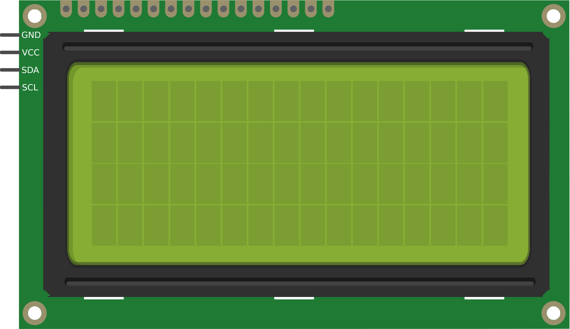
The I2C/LCD1602 BLUE SCREEN is a 16x2 character LCD display module equipped with an I2C interface. This component simplifies the process of connecting the display to microcontrollers by reducing the number of required pins. It features a blue backlight with white text, making it ideal for clear and readable text output in various lighting conditions.
Explore Projects Built with I2C/LCD1602 BLUE SCREEN


Explore Projects Built with I2C/LCD1602 BLUE SCREEN
Common Applications and Use Cases
- Displaying sensor data in IoT projects
- User interfaces for embedded systems
- Menu systems for DIY electronics
- Debugging and status monitoring in microcontroller projects
Technical Specifications
The I2C/LCD1602 BLUE SCREEN is designed for ease of use and compatibility with a wide range of microcontrollers, including Arduino, Raspberry Pi, and others.
Key Technical Details
| Parameter | Value |
|---|---|
| Display Type | 16x2 character LCD |
| Interface | I2C (Inter-Integrated Circuit) |
| Backlight Color | Blue |
| Text Color | White |
| Operating Voltage | 5V DC |
| Current Consumption | ~20mA (with backlight) |
| I2C Address (Default) | 0x27 or 0x3F (varies by model) |
| Dimensions | 80mm x 36mm x 12mm |
Pin Configuration and Descriptions
The I2C interface reduces the number of pins required to connect the LCD to just four. Below is the pin configuration:
| Pin Name | Description |
|---|---|
| GND | Ground (0V) |
| VCC | Power supply (5V) |
| SDA | Serial Data Line (I2C data) |
| SCL | Serial Clock Line (I2C clock) |
Usage Instructions
How to Use the Component in a Circuit
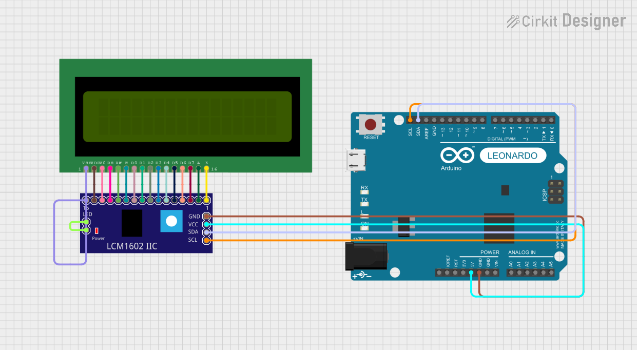
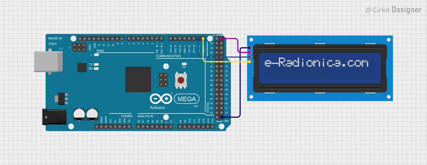
Wiring the LCD to a Microcontroller:
- Connect the
GNDpin of the LCD to the ground pin of the microcontroller. - Connect the
VCCpin of the LCD to the 5V power pin of the microcontroller. - Connect the
SDApin of the LCD to the I2C data pin of the microcontroller (e.g., A4 on Arduino UNO). - Connect the
SCLpin of the LCD to the I2C clock pin of the microcontroller (e.g., A5 on Arduino UNO).
- Connect the
Install Required Libraries:
- For Arduino, install the
LiquidCrystal_I2Clibrary via the Library Manager in the Arduino IDE.
- For Arduino, install the
Upload Example Code:
- Use the following example code to display text on the LCD:
#include <Wire.h>
#include <LiquidCrystal_I2C.h>

// Initialize the LCD with the I2C address (default is 0x27 or 0x3F)
// Adjust the address if your module uses a different one
LiquidCrystal_I2C lcd(0x27, 16, 2);

void setup() {
  lcd.begin(); // Initialize the LCD
  lcd.backlight(); // Turn on the backlight
  lcd.setCursor(0, 0); // Set cursor to the first row, first column
  lcd.print("Hello, World!"); // Print text on the first row
  lcd.setCursor(0, 1); // Set cursor to the second row, first column
  lcd.print("I2C LCD1602"); // Print text on the second row
}

void loop() {
  // No actions in the loop for this example
}
Important Considerations and Best Practices
- I2C Address: Verify the I2C address of your module. If the default address (0x27) does not work, use an I2C scanner sketch to detect the correct address.
- Power Supply: Ensure a stable 5V power supply to avoid flickering or malfunctioning of the display.
- Contrast Adjustment: Some modules include a potentiometer for adjusting the contrast. Turn the potentiometer to achieve optimal text visibility.
- Backlight Control: The backlight can be turned off programmatically using the
noBacklight()function in theLiquidCrystal_I2Clibrary.
Troubleshooting and FAQs
Common Issues and Solutions
No Text Displayed on the LCD:
- Ensure the wiring is correct and matches the pin configuration.
- Verify the I2C address using an I2C scanner sketch.
- Adjust the contrast potentiometer if the text is faint or invisible.
Flickering or Unstable Display:
- Check the power supply for stability and ensure it provides 5V.
- Avoid using long or thin wires for power and data connections.
Backlight Not Turning On:
- Confirm that the
lcd.backlight()function is called in the code. - Check the solder joints on the I2C backpack for any loose connections.
- Confirm that the
Incorrect Characters Displayed:
- Verify that the correct library (
LiquidCrystal_I2C) is installed and used. - Ensure the I2C address in the code matches the module's address.
- Verify that the correct library (
FAQs
Q: How do I find the I2C address of my LCD module?
A: Use an I2C scanner sketch available in the Arduino IDE examples. It will detect and display the address of all connected I2C devices.
Q: Can I use this module with a 3.3V microcontroller?
A: While the module is designed for 5V operation, some models may work with 3.3V logic. Check the module's datasheet or use a logic level shifter for compatibility.
Q: Can I display custom characters on the LCD?
A: Yes, the LiquidCrystal_I2C library supports custom characters. Refer to the library documentation for details on creating and displaying custom characters.
Q: Is it possible to control multiple LCDs with one microcontroller?
A: Yes, you can connect multiple LCDs by assigning each a unique I2C address. Modify the address on the I2C backpack if necessary.
By following this documentation, you can effectively integrate the I2C/LCD1602 BLUE SCREEN into your projects and troubleshoot common issues with ease.