How to Use STM32F103C8T6 Type C: Examples, Pinouts, and Specs
Introduction
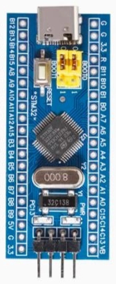
The STM32F103C8T6 Type C is a high-performance, low-power microcontroller from the STM32 family, manufactured by STMicroelectronics (STM). It is based on the ARM Cortex-M3 32-bit RISC core, operating at a frequency of up to 72 MHz. This microcontroller is widely used in embedded systems due to its robust feature set, including a variety of peripherals, low power consumption, and high processing power.
The "Type C" variant refers to the integration of a USB Type-C interface, making it ideal for modern applications requiring USB connectivity. It is commonly used in applications such as industrial automation, IoT devices, robotics, and consumer electronics.
Explore Projects Built with STM32F103C8T6 Type C


Explore Projects Built with STM32F103C8T6 Type C
Technical Specifications
Key Technical Details
- Core: ARM Cortex-M3 32-bit RISC
- Operating Frequency: Up to 72 MHz
- Flash Memory: 64 KB
- SRAM: 20 KB
- GPIO Pins: 37 (multiplexed with other functions)
- Communication Interfaces:
- 2x I2C
- 3x USART
- 2x SPI
- 1x USB (Type-C)
- Timers: 3x 16-bit timers, 1x 16-bit PWM timer
- ADC: 12-bit, up to 16 channels
- Operating Voltage: 2.0V to 3.6V
- Power Consumption: Low-power modes available
- Package: LQFP-48 (48-pin)
Pin Configuration and Descriptions
The STM32F103C8T6 Type C has 48 pins. Below is a table highlighting key pins and their functions:
| Pin Number | Pin Name | Function | Description |
|---|---|---|---|
| 1 | VDD | Power Supply | 3.3V power input |
| 2 | VSS | Ground | Ground connection |
| 10 | PA0 | GPIO/ADC_IN0 | General-purpose I/O or ADC input channel |
| 14 | PB6 | I2C1_SCL | I2C1 clock line |
| 15 | PB7 | I2C1_SDA | I2C1 data line |
| 23 | PA9 | USART1_TX | UART transmit pin |
| 24 | PA10 | USART1_RX | UART receive pin |
| 28 | PA12 | USB_DP | USB data positive |
| 29 | PA11 | USB_DM | USB data negative |
| 48 | NRST | Reset | Active-low reset pin |
For a complete pinout, refer to the STM32F103C8T6 datasheet.
Usage Instructions
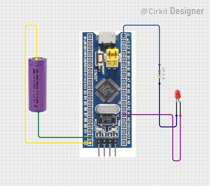
How to Use the Component in a Circuit
- Power Supply: Connect the VDD pin to a 3.3V power source and the VSS pin to ground.
- USB Type-C Interface: Use PA11 (USB_DM) and PA12 (USB_DP) for USB communication. Ensure proper termination resistors are used as per the USB standard.
- Programming: Use the SWD (Serial Wire Debug) interface for programming and debugging. Connect SWDIO and SWCLK to the programmer.
- GPIO Configuration: Configure GPIO pins as input, output, or alternate function using the STM32 HAL (Hardware Abstraction Layer) library.
- Clock Configuration: Set up the system clock using the internal or external oscillator for optimal performance.
Important Considerations and Best Practices
- Decoupling Capacitors: Place 0.1 µF decoupling capacitors close to the VDD pins to reduce noise.
- USB Protection: Use ESD protection diodes on USB_DP and USB_DM lines to protect against voltage spikes.
- Boot Mode Selection: Use the BOOT0 pin to select between bootloader and user application modes.
- Clock Source: For USB applications, ensure the external crystal oscillator is configured correctly to meet USB timing requirements.
Example Code for Arduino UNO Integration
Although the STM32F103C8T6 is not directly compatible with Arduino UNO, it can be programmed using the Arduino IDE with the STM32 core installed. Below is an example of blinking an LED connected to pin PA5:
// Include the STM32 HAL library
#include <Arduino.h>

// Define the LED pin
#define LED_PIN PA5

void setup() {
  // Initialize the LED pin as an output
  pinMode(LED_PIN, OUTPUT);
}

void loop() {
  // Turn the LED on
  digitalWrite(LED_PIN, HIGH);
  delay(1000); // Wait for 1 second

  // Turn the LED off
  digitalWrite(LED_PIN, LOW);
  delay(1000); // Wait for 1 second
}
Troubleshooting and FAQs
Common Issues and Solutions
Microcontroller Not Responding:
- Cause: Incorrect power supply or faulty connections.
- Solution: Verify the VDD and VSS connections and ensure a stable 3.3V supply.
USB Communication Fails:
- Cause: Improper termination resistors or incorrect clock configuration.
- Solution: Check the USB_DP and USB_DM lines for proper termination. Ensure the external crystal oscillator is configured correctly.
Cannot Program the Microcontroller:
- Cause: BOOT0 pin is not set correctly or SWD connections are incorrect.
- Solution: Ensure the BOOT0 pin is set to the correct mode. Verify SWDIO and SWCLK connections.
GPIO Pins Not Functioning:
- Cause: Pins not configured properly in software.
- Solution: Double-check the GPIO initialization code and ensure the correct pin mode is set.
FAQs
Q: Can I use the STM32F103C8T6 with a 5V power supply?
A: No, the STM32F103C8T6 operates at 2.0V to 3.6V. Use a voltage regulator to step down 5V to 3.3V.Q: How do I enable USB functionality?
A: Configure the USB peripheral in the STM32 HAL library and ensure the external crystal oscillator is set up correctly.Q: Can I use the Arduino IDE to program this microcontroller?
A: Yes, install the STM32 core in the Arduino IDE to program the STM32F103C8T6.Q: What is the maximum current the GPIO pins can source/sink?
A: Each GPIO pin can source/sink up to 25 mA, but the total current for all GPIOs should not exceed 150 mA.
This concludes the documentation for the STM32F103C8T6 Type C microcontroller. For further details, refer to the official datasheet and reference manual provided by STMicroelectronics.