How to Use AdaGator Side White: Examples, Pinouts, and Specs

 Design with AdaGator Side White in Cirkit Designer
Introduction
The AdaGator Side White is a versatile prototyping board tailored for Adafruit's Feather development boards. It facilitates rapid prototyping by offering a solderless connection platform for various electronic components and modules. This board is ideal for hobbyists, educators, and professionals who require a quick and reliable way to prototype their projects with Feather boards.
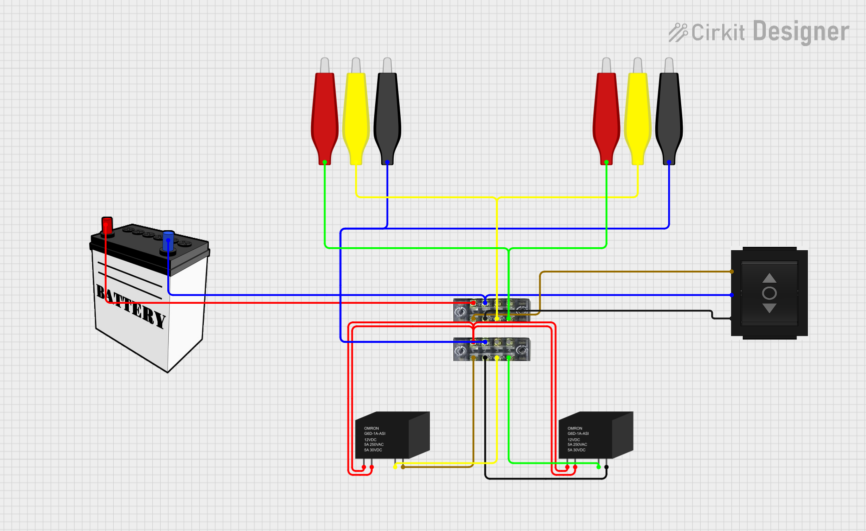
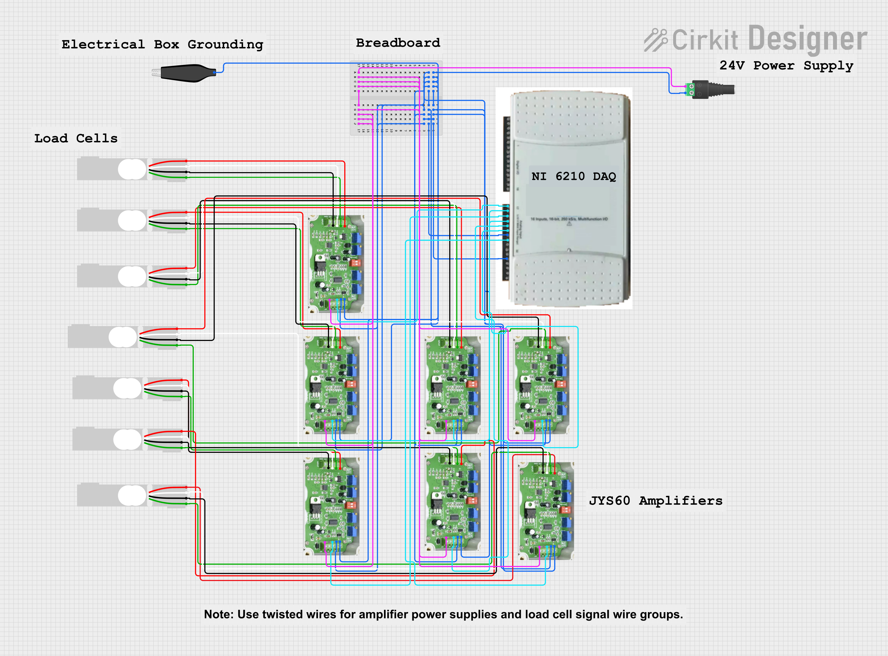
Explore Projects Built with AdaGator Side White

 Open Project in Cirkit Designer
 Open Project in Cirkit Designer
 Open Project in Cirkit Designer
 Open Project in Cirkit Designer
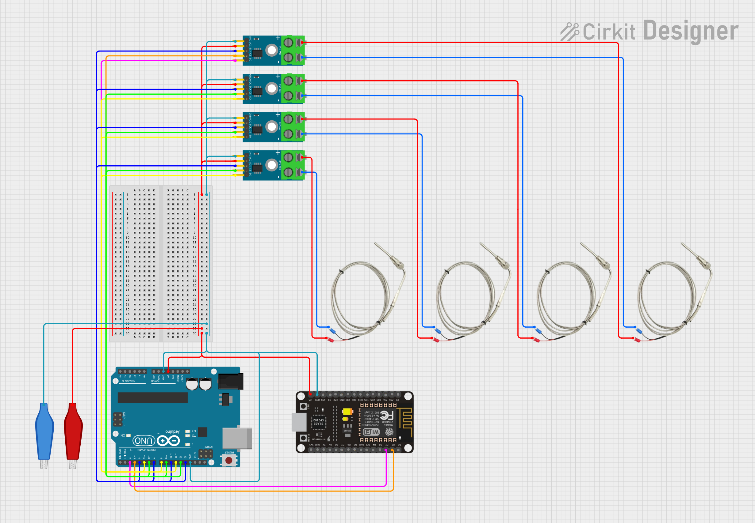
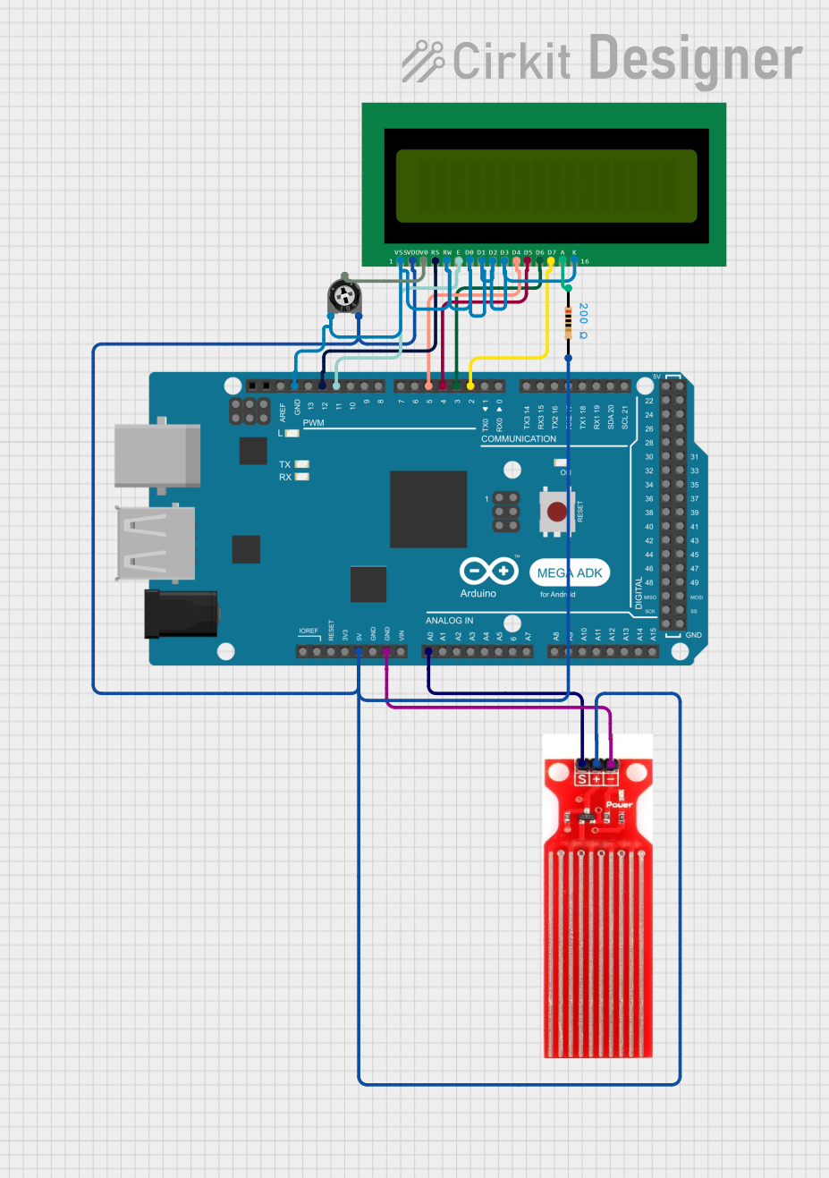
Explore Projects Built with AdaGator Side White

 Open Project in Cirkit Designer
 Open Project in Cirkit Designer
 Open Project in Cirkit Designer
 Open Project in Cirkit Designer
Common Applications and Use Cases
- Rapid prototyping of electronic circuits
- Educational projects and learning platforms
- IoT device development
- Wearable electronics
- Temporary setups for testing and debugging
Technical Specifications
Key Technical Details
- Compatibility: Designed to interface with Adafruit Feather boards
- Connection Type: Solderless breadboard-style
- Dimensions: Matches the Adafruit Feather form factor
- Material: High-quality FR4 with white solder mask
Pin Configuration and Descriptions
| Pin Number | Description | Notes |
|---|---|---|
| 1-xx | Corresponding to Feather Board Pins | Connects directly to Feather pins |
| A1-Ax | Analog Input/Output Pins | For analog signals |
| D1-Dx | Digital Input/Output Pins | For digital signals |
| GND | Ground Connections | Common ground for circuits |
| 3V3 | 3.3V Power Rail | Power supply from Feather |
| VIN | Voltage Input | External power supply input |
Note: Replace 'xx' and 'x' with the actual number of pins available on the AdaGator Side White board, which should match the specific Feather board being used.
Usage Instructions
How to Use the Component in a Circuit
Mounting the Feather Board:
- Align the pins of your Feather board with the corresponding connectors on the AdaGator Side White.
- Gently press down to ensure a secure and proper connection.
Connecting Components:
- Insert the leads of your components into the breadboard-style holes on the AdaGator Side White.
- Ensure that connections are firm and that there is no short-circuiting between adjacent pins.
Powering the Circuit:
- Power can be supplied through the Feather board's USB connection or via an external power source connected to the VIN pin.
Testing the Circuit:
- Once all components are connected, you can upload your code to the Feather board and test the circuit.
Important Considerations and Best Practices
- Always power down the Feather board before making or changing connections on the AdaGator Side White.
- Double-check all connections for correctness before applying power to prevent damage to the board or components.
- Use jumper wires of appropriate lengths to avoid a cluttered and confusing layout.
- Plan your circuit layout to minimize crossing wires, which can lead to confusion and errors.
Troubleshooting and FAQs
Common Issues Users Might Face
- Loose Connections: Ensure that all components and wires are firmly inserted into the AdaGator Side White's connectors.
- Incorrect Wiring: Double-check the circuit against the schematic to ensure all connections are correct.
- Power Issues: Verify that the Feather board is properly powered and that the power supply is adequate for the connected components.
Solutions and Tips for Troubleshooting
- If the circuit is not working as expected, disconnect the power and carefully inspect all connections.
- Use a multimeter to check for continuity and correct voltages at different points in the circuit.
- Simplify the circuit by removing non-essential components and gradually add them back to isolate the issue.
FAQs
Q: Can I use the AdaGator Side White with non-Feather boards? A: The AdaGator Side White is designed specifically for Adafruit Feather boards. Using it with other boards may require modifications or may not be possible.
Q: How many components can I connect to the AdaGator Side White? A: The number of components you can connect depends on the complexity of your circuit and the number of available connection points on the board.
Q: Do I need to solder any connections on the AdaGator Side White? A: No, the AdaGator Side White is designed for solderless prototyping. However, for permanent installations, soldering may be preferred for reliability.
Example Code for Arduino UNO
// Example code for blinking an LED connected to the AdaGator Side White
// and an Adafruit Feather board.

void setup() {
  // Initialize the digital pin as an output.
  pinMode(13, OUTPUT); // LED on most Feather boards attached to pin 13
}

void loop() {
  digitalWrite(13, HIGH);   // Turn the LED on
  delay(1000);              // Wait for a second
  digitalWrite(13, LOW);    // Turn the LED off
  delay(1000);              // Wait for a second
}
Note: The example code provided is for illustrative purposes and assumes the use of an Adafruit Feather board compatible with Arduino IDE. The pin number and functionality may vary depending on the specific Feather board used.