
How to Use EC11 bare encoder - A C B and push S1 S2: Examples, Pinouts, and Specs
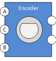
 Design with EC11 bare encoder - A C B and push S1 S2 in Cirkit Designer
Introduction
The EC11 bare encoder is a rotary encoder that provides incremental position feedback through its A and B outputs. It also features a built-in push-button switch (S1) for additional functionality. This component is widely used in user interfaces for tasks such as adjusting settings, navigating menus, or controlling volume. Its compact design and versatility make it a popular choice for both hobbyist and professional applications.
Explore Projects Built with EC11 bare encoder - A C B and push S1 S2
 Open Project in Cirkit Designer
 Open Project in Cirkit Designer
 Open Project in Cirkit Designer
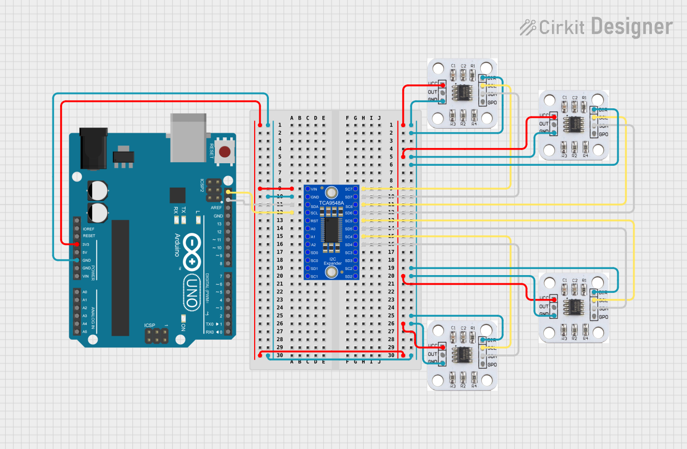 Open Project in Cirkit Designer
Explore Projects Built with EC11 bare encoder - A C B and push S1 S2
Open Project in Cirkit DesignerOpen Project in Cirkit DesignerOpen Project in Cirkit DesignerOpen Project in Cirkit DesignerCommon Applications:
- Volume control in audio devices
- Menu navigation in embedded systems
- Position feedback in robotics
- User input for industrial control panels
Technical Specifications
Key Technical Details:
- Type: Incremental rotary encoder with push-button
- Operating Voltage: 5V DC (typical)
- Output Type: Digital (A, B, and push-button signals)
- Resolution: 20 pulses per revolution (PPR)
- Switch Type: Momentary push-button
- Operating Temperature: -30°C to +70°C
- Shaft Diameter: 6mm
- Mounting Type: PCB mount
Pin Configuration and Descriptions:
The EC11 encoder typically has 5 pins. The table below describes each pin:
| Pin Name | Description |
|---|---|
| A | Output signal A (quadrature signal) |
| B | Output signal B (quadrature signal) |
| C (GND) | Common ground for the encoder |
| S1 | Push-button switch signal (normally open) |
| S2 (VCC) | Power supply for the encoder (typically 5V) |
Usage Instructions
How to Use the EC11 Encoder in a Circuit:
Connect the Power Supply:
- Connect the S2 pin to a 5V DC power source.
- Connect the C pin to the ground (GND) of your circuit.
Connect the Output Signals:
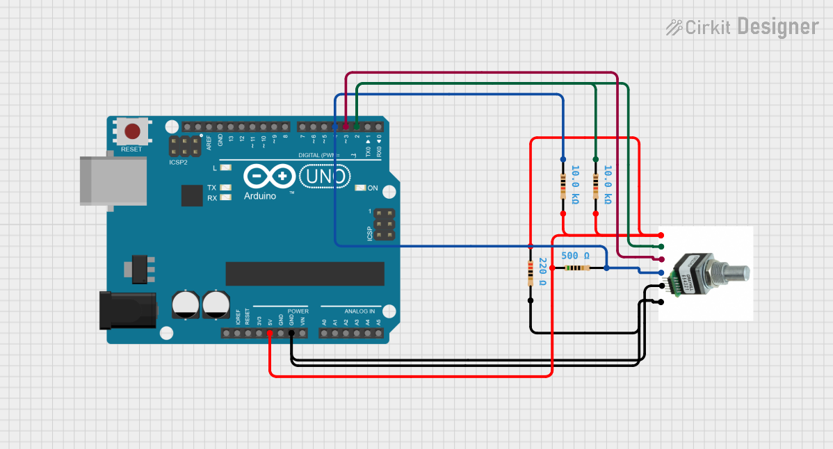
- Connect the A and B pins to digital input pins on your microcontroller. These pins will provide the quadrature signals for detecting rotation direction and steps.
Connect the Push-Button:
- Connect the S1 pin to a digital input pin on your microcontroller. Use a pull-down resistor (e.g., 10kΩ) to ensure a stable signal when the button is not pressed.
Read the Signals:
- Monitor the A and B signals to detect rotation direction and steps.
- Monitor the S1 signal to detect button presses.
Important Considerations:
- Debouncing: Both the rotary encoder and the push-button may produce noisy signals. Use hardware (capacitors) or software (debouncing algorithms) to filter out noise.
- Pull-Up/Pull-Down Resistors: Ensure proper use of pull-up or pull-down resistors for stable signal readings.
- Mechanical Limitations: Avoid applying excessive force to the encoder shaft to prevent damage.
Example Code for Arduino UNO:
The following code demonstrates how to use the EC11 encoder with an Arduino UNO to detect rotation and button presses.
// Pin definitions
const int pinA = 2;  // Connect to encoder pin A
const int pinB = 3;  // Connect to encoder pin B
const int buttonPin = 4;  // Connect to encoder push-button (S1)

// Variables to track encoder state
volatile int encoderPosition = 0;
int lastEncoded = 0;

// Button state
int lastButtonState = HIGH;

void setup() {
  pinMode(pinA, INPUT_PULLUP);  // Enable pull-up resistor for pin A
  pinMode(pinB, INPUT_PULLUP);  // Enable pull-up resistor for pin B
  pinMode(buttonPin, INPUT_PULLUP);  // Enable pull-up resistor for button

  // Attach interrupts for encoder pins
  attachInterrupt(digitalPinToInterrupt(pinA), updateEncoder, CHANGE);
  attachInterrupt(digitalPinToInterrupt(pinB), updateEncoder, CHANGE);

  Serial.begin(9600);  // Initialize serial communication
}

void loop() {
  // Read the button state
  int buttonState = digitalRead(buttonPin);
  if (buttonState == LOW && lastButtonState == HIGH) {
    Serial.println("Button Pressed!");
  }
  lastButtonState = buttonState;

  // Print the encoder position
  Serial.print("Encoder Position: ");
  Serial.println(encoderPosition);

  delay(100);  // Small delay for readability
}

void updateEncoder() {
  // Read the current state of A and B
  int MSB = digitalRead(pinA);  // Most significant bit
  int LSB = digitalRead(pinB);  // Least significant bit

  int encoded = (MSB << 1) | LSB;  // Combine A and B into a single value
  int sum = (lastEncoded << 2) | encoded;  // Track state changes

  // Determine direction based on state transitions
  if (sum == 0b1101 || sum == 0b0100 || sum == 0b0010 || sum == 0b1011) {
    encoderPosition++;
  } else if (sum == 0b1110 || sum == 0b0111 || sum == 0b0001 || sum == 0b1000) {
    encoderPosition--;
  }

  lastEncoded = encoded;  // Update the last encoded value
}
Notes on the Code:
- The
updateEncoderfunction uses interrupts to detect changes in the A and B signals, ensuring accurate position tracking. - The push-button is read in the
loopfunction, and a message is printed when it is pressed.
Troubleshooting and FAQs
Common Issues:
No Response from the Encoder:
- Ensure the power supply (S2 and C pins) is correctly connected.
- Verify that the A and B pins are connected to the correct microcontroller pins.
Incorrect Position Readings:
- Check for loose connections or poor soldering.
- Implement proper debouncing in software or hardware.
Button Not Detected:
- Ensure the S1 pin is connected to a digital input pin with a pull-down resistor.
- Verify that the button is not physically damaged.
FAQs:
Q: Can I use the EC11 encoder with a 3.3V microcontroller?
A: Yes, but ensure the encoder operates reliably at 3.3V. If not, use a level shifter.Q: How do I increase the resolution of the encoder?
A: The resolution is fixed at 20 PPR. However, you can use software to detect both rising and falling edges of the A and B signals for higher precision.Q: What is the lifespan of the EC11 encoder?
A: The EC11 encoder typically has a lifespan of 30,000 to 50,000 cycles, depending on usage conditions.
By following this documentation, you can effectively integrate the EC11 bare encoder into your projects and troubleshoot common issues.