Cirkit Designer Logo
Cirkit Designer
Your all-in-one circuit design IDE
Home / 
Component Documentation

How to Use Papa_Soundie: Examples, Pinouts, and Specs

Image of Papa_Soundie
Cirkit Designer LogoDesign with Papa_Soundie in Cirkit Designer

Introduction

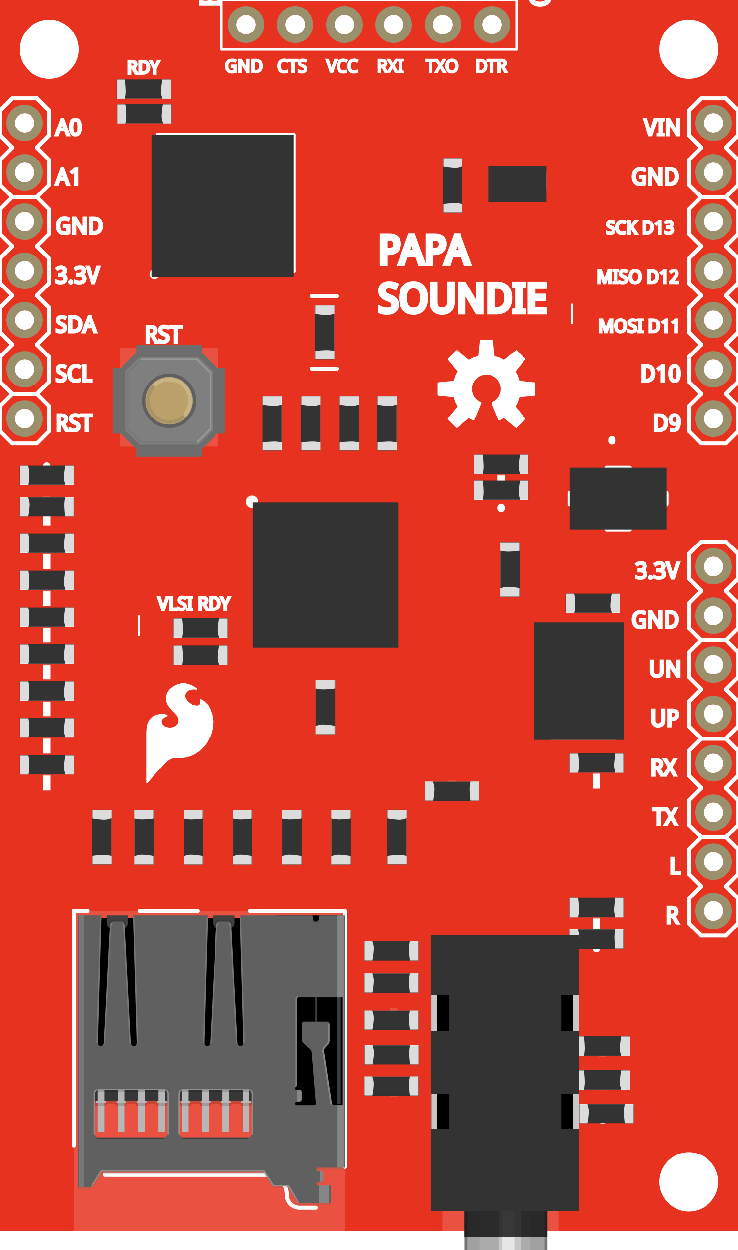
The Papa Soundie is an innovative audio playback module designed to make adding sound to your projects easy and efficient. It is capable of playing audio files stored on a microSD card and supports popular audio formats such as MP3 and WAV. The module can be controlled via serial commands, making it a versatile component for a wide range of applications, including interactive art installations, sound effects for toys, or as a voice prompt system for various electronic devices.

Explore Projects Built with Papa_Soundie

Use Cirkit Designer to design, explore, and prototype these projects online. Some projects support real-time simulation. Click "Open Project" to start designing instantly!
Adafruit Audio FX Mini Sound Board Dual Loudspeaker Audio System
Image of Adafruit Audio FX Sound Board: A project utilizing Papa_Soundie in a practical application
This circuit features an Adafruit Audio FX Mini Sound Board connected to two loudspeakers. The sound board's left and right audio channels (L_AC and R_AC) are connected to the respective pins of the loudspeakers, enabling stereo audio output. The sound board is powered through its VIN pin, and all components share a common ground.
Cirkit Designer LogoOpen Project in Cirkit Designer
Battery-Powered Piezo Buzzer with Pushbutton Activation
Image of wallet: A project utilizing Papa_Soundie in a practical application
This circuit appears to be a simple sound generation system controlled by a pushbutton. When the button is pressed, the battery powers the Piezo Speaker through a BC547 transistor, which likely acts as a switch to drive the speaker. A diode is connected to the base of the transistor, possibly for protection against reverse currents or to shape the input signal to the base.
Cirkit Designer LogoOpen Project in Cirkit Designer
Arduino 101 Sound-Activated Piezo Speaker System
Image of noise detector: A project utilizing Papa_Soundie in a practical application
This circuit features an Arduino 101 microcontroller connected to a sound sensor and a piezo speaker. The sound sensor's output is connected to the Arduino's A0 analog input, allowing the microcontroller to process audio signal levels. The piezo speaker is connected to digital pin D8 and ground (GND), enabling the Arduino to generate audio signals or feedback based on the sensor input.
Cirkit Designer LogoOpen Project in Cirkit Designer
Arduino UNO Melody Player with Piezo Speaker
Image of piezo buzzer basic tone - sim test: A project utilizing Papa_Soundie in a practical application
This circuit uses an Arduino UNO to drive a piezo speaker, generating a melody. The Arduino is programmed to output different frequencies on pin D9, which are then converted into sound by the piezo speaker connected between pin D9 and GND.
Cirkit Designer LogoOpen Project in Cirkit Designer

Explore Projects Built with Papa_Soundie

Use Cirkit Designer to design, explore, and prototype these projects online. Some projects support real-time simulation. Click "Open Project" to start designing instantly!
Image of Adafruit Audio FX Sound Board: A project utilizing Papa_Soundie in a practical application
Adafruit Audio FX Mini Sound Board Dual Loudspeaker Audio System
This circuit features an Adafruit Audio FX Mini Sound Board connected to two loudspeakers. The sound board's left and right audio channels (L_AC and R_AC) are connected to the respective pins of the loudspeakers, enabling stereo audio output. The sound board is powered through its VIN pin, and all components share a common ground.
Cirkit Designer LogoOpen Project in Cirkit Designer
Image of wallet: A project utilizing Papa_Soundie in a practical application
Battery-Powered Piezo Buzzer with Pushbutton Activation
This circuit appears to be a simple sound generation system controlled by a pushbutton. When the button is pressed, the battery powers the Piezo Speaker through a BC547 transistor, which likely acts as a switch to drive the speaker. A diode is connected to the base of the transistor, possibly for protection against reverse currents or to shape the input signal to the base.
Cirkit Designer LogoOpen Project in Cirkit Designer
Image of noise detector: A project utilizing Papa_Soundie in a practical application
Arduino 101 Sound-Activated Piezo Speaker System
This circuit features an Arduino 101 microcontroller connected to a sound sensor and a piezo speaker. The sound sensor's output is connected to the Arduino's A0 analog input, allowing the microcontroller to process audio signal levels. The piezo speaker is connected to digital pin D8 and ground (GND), enabling the Arduino to generate audio signals or feedback based on the sensor input.
Cirkit Designer LogoOpen Project in Cirkit Designer
Image of piezo buzzer basic tone - sim test: A project utilizing Papa_Soundie in a practical application
Arduino UNO Melody Player with Piezo Speaker
This circuit uses an Arduino UNO to drive a piezo speaker, generating a melody. The Arduino is programmed to output different frequencies on pin D9, which are then converted into sound by the piezo speaker connected between pin D9 and GND.
Cirkit Designer LogoOpen Project in Cirkit Designer

Technical Specifications

Key Technical Details

  • Supported Audio Formats: MP3, WAV
  • Storage: microSD card slot (supports up to 32GB SDHC)
  • Output: Stereo audio output via a 3.5mm headphone jack
  • Control Interface: Serial UART
  • Supply Voltage: 3.3V to 5.5V
  • Current Consumption: 20mA idle, 50mA playing sound (typical)
  • Dimensions: 44mm x 28mm

Pin Configuration and Descriptions

Pin Number Pin Name Description
1 VCC Power supply (3.3V to 5.5V)
2 GND Ground
3 TX Transmit data (connect to RX of controller)
4 RX Receive data (connect to TX of controller)
5 SPK+ Speaker positive output
6 SPK- Speaker negative output

Usage Instructions

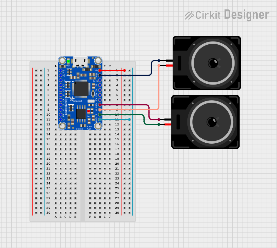
Connecting to a Circuit

  1. Power Supply: Connect the VCC pin to a 3.3V to 5.5V power source and the GND pin to the ground.
  2. Serial Communication: Connect the TX pin of the Papa Soundie to the RX pin of your microcontroller (e.g., Arduino UNO) and the RX pin to the TX pin of the microcontroller.
  3. Audio Output: Connect a speaker or an audio input device to the SPK+ and SPK- pins.

Important Considerations and Best Practices

  • Ensure that the power supply is within the specified voltage range to prevent damage.
  • Format the microSD card to FAT32 and store audio files in the root directory.
  • Use a level shifter if you are interfacing with a microcontroller operating at a different logic level.
  • Keep the audio file names short and follow the 8.3 naming convention (e.g., sound01.mp3).

Example Code for Arduino UNO

#include <SoftwareSerial.h>

SoftwareSerial soundieSerial(10, 11); // RX, TX

void setup() {
  // Start the serial communication with the Papa Soundie
  soundieSerial.begin(9600);
}

void loop() {
  // Play the first track on the SD card
  soundieSerial.write('O');
  soundieSerial.write(1);
  delay(5000); // Wait for 5 seconds

  // Stop the playback
  soundieSerial.write('X');
  delay(1000); // Wait for 1 second before the next command
}

Troubleshooting and FAQs

Common Issues

  • No Sound Output: Ensure the speaker is properly connected and the audio file is in the correct format and naming convention.
  • Distorted Sound: Check if the speaker impedance matches the Papa Soundie's specifications and that the audio file's bitrate is not too high.
  • Module Not Responding: Verify the serial connections and ensure the microcontroller is operating at the correct baud rate.

Solutions and Tips

  • If the Papa Soundie is not playing sound, recheck the wiring and ensure the SD card is properly inserted and formatted.
  • For distorted sound, try a different speaker or re-encode the audio file with a lower bitrate.
  • In case of communication issues, use a logic analyzer or oscilloscope to check the serial data lines for proper signals.

FAQs

Q: Can I connect headphones directly to the Papa Soundie? A: Yes, you can connect headphones directly to the 3.5mm jack, but ensure the volume is at a safe level.

Q: How do I change the volume of playback? A: Volume control can be implemented in your code by sending the appropriate serial commands to the Papa Soundie.

Q: What is the maximum size of the SD card that can be used? A: The Papa Soundie supports microSD cards up to 32GB in size.

For further assistance, consult the Papa Soundie's community forum or contact technical support.