How to Use Pressure diff sensor: Examples, Pinouts, and Specs
Introduction
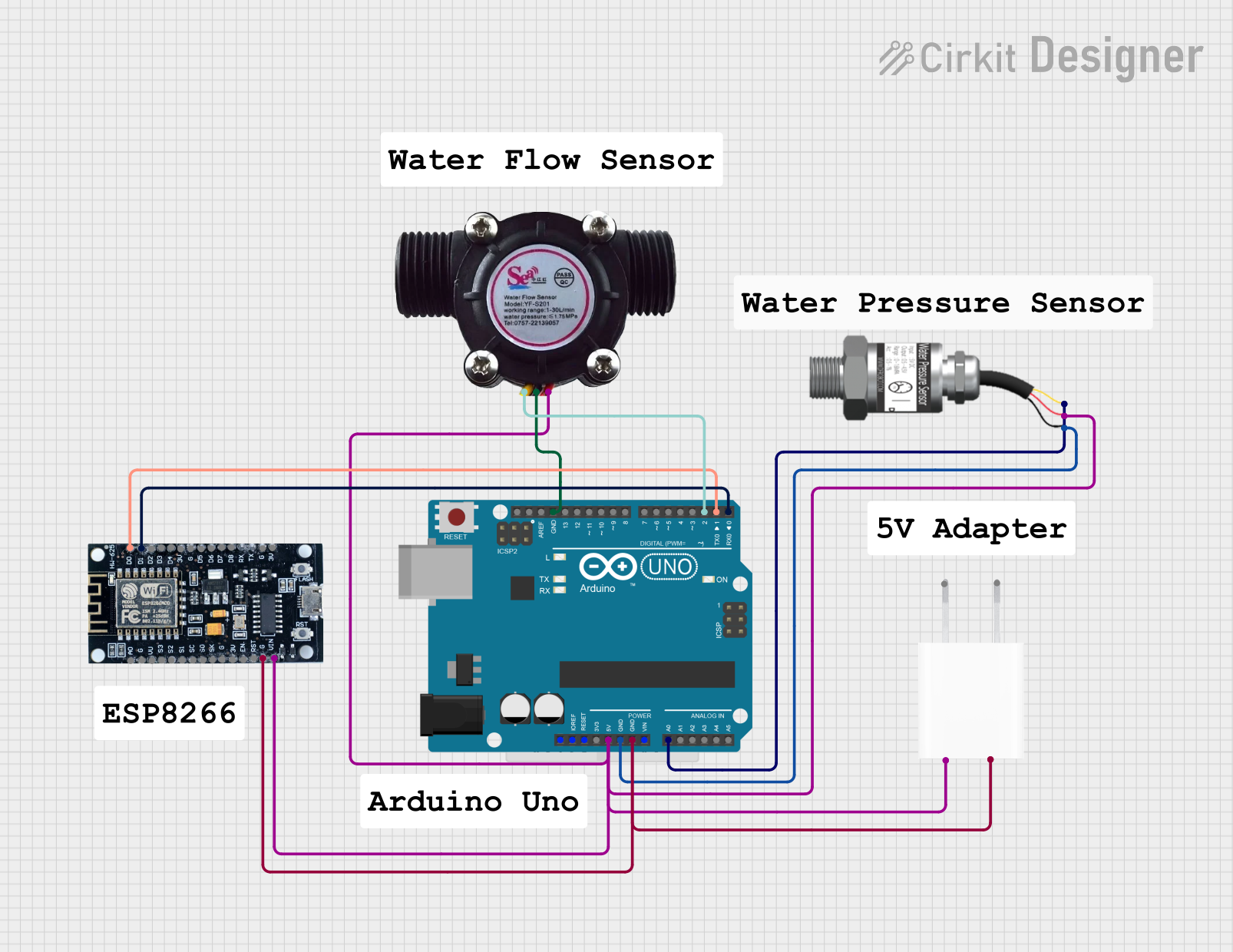
A Pressure Differential Sensor, commonly referred to as a Pressure Diff Sensor, is a device designed to measure the difference in pressure between two points. It is widely used in applications such as HVAC systems, fluid dynamics, and industrial processes to monitor and control pressure variations. By providing accurate pressure readings, this sensor ensures optimal system performance and safety.
Explore Projects Built with Pressure diff sensor
Explore Projects Built with Pressure diff sensor
Common Applications:
- HVAC systems for airflow monitoring and filter performance evaluation.
- Industrial process control to measure pressure drops across components.
- Fluid dynamics experiments to analyze flow behavior.
- Medical devices such as ventilators and CPAP machines.
- Automotive systems for turbocharger and exhaust pressure monitoring.
Technical Specifications
Below are the general technical specifications for a typical Pressure Diff Sensor. Always refer to the datasheet of your specific model for precise details.
Key Specifications:
- Operating Voltage: 3.3V to 5V DC
- Output Signal: Analog (0.5V to 4.5V) or Digital (I2C/SPI)
- Pressure Range: ±1 kPa to ±100 kPa (varies by model)
- Accuracy: ±1% of full-scale reading
- Operating Temperature: -20°C to 85°C
- Response Time: <5 ms
- Port Type: Dual port (high-pressure and low-pressure)
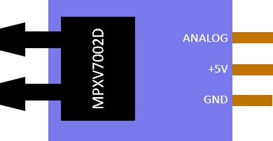
Pin Configuration:
The pinout for a typical 4-pin Pressure Diff Sensor is as follows:
| Pin | Name | Description |
|---|---|---|
| 1 | VCC | Power supply input (3.3V or 5V DC) |
| 2 | GND | Ground connection |
| 3 | OUT (Analog) | Analog output signal proportional to pressure |
| 4 | SDA/SCL (I2C) | Data/Clock lines for digital communication (if applicable) |
For digital models, pins 3 and 4 may be used for I2C or SPI communication.
Usage Instructions
How to Use the Component in a Circuit:
Power the Sensor:
- Connect the VCC pin to a 3.3V or 5V power source, depending on the sensor's specifications.
- Connect the GND pin to the ground of your circuit.
Connect the Output:
- For analog sensors, connect the OUT pin to an analog input pin of your microcontroller.
- For digital sensors, connect the SDA and SCL pins to the corresponding I2C pins on your microcontroller.
Pressure Ports:
- Attach tubing to the high-pressure and low-pressure ports. Ensure a secure fit to prevent leaks.
- The sensor will measure the pressure difference between these two ports.
Read the Data:
- For analog sensors, read the voltage output and convert it to pressure using the sensor's transfer function.
- For digital sensors, use I2C or SPI communication to retrieve pressure data.
Important Considerations:
- Calibration: Some sensors require calibration before use. Follow the manufacturer's instructions for calibration procedures.
- Pressure Range: Ensure the pressure difference does not exceed the sensor's maximum rating to avoid damage.
- Environmental Conditions: Avoid exposing the sensor to extreme temperatures, moisture, or corrosive substances.
- Tubing: Use appropriate tubing materials that are compatible with the fluid or gas being measured.
Example Code for Arduino UNO (Analog Sensor):
// Example code to read data from an analog Pressure Diff Sensor
// and display the pressure difference on the Serial Monitor.

const int sensorPin = A0; // Connect the OUT pin of the sensor to A0
float sensorVoltage = 0.0; // Variable to store the sensor's output voltage
float pressure = 0.0;      // Variable to store the calculated pressure

void setup() {
  Serial.begin(9600); // Initialize serial communication at 9600 baud
}

void loop() {
  // Read the analog voltage from the sensor
  int sensorValue = analogRead(sensorPin);

  // Convert the analog value (0-1023) to voltage (0-5V for a 5V system)
  sensorVoltage = sensorValue * (5.0 / 1023.0);

  // Convert the voltage to pressure using the sensor's transfer function
  // Example: Pressure (kPa) = (Voltage - 0.5) * (Pressure Range / 4.0)
  // Replace 'Pressure Range' with the sensor's full-scale range (e.g., 100 kPa)
  pressure = (sensorVoltage - 0.5) * (100.0 / 4.0);

  // Print the pressure to the Serial Monitor
  Serial.print("Pressure Difference: ");
  Serial.print(pressure);
  Serial.println(" kPa");

  delay(1000); // Wait for 1 second before the next reading
}
Troubleshooting and FAQs
Common Issues:
No Output Signal:
- Check the power supply voltage and ensure proper connections.
- Verify that the sensor is within its operating temperature range.
Inaccurate Readings:
- Ensure the tubing is securely connected and free of leaks.
- Calibrate the sensor if required.
- Verify that the pressure difference is within the sensor's specified range.
Fluctuating Output:
- Check for electrical noise in the circuit. Use decoupling capacitors if necessary.
- Ensure stable pressure conditions during measurement.
No Communication (Digital Sensors):
- Verify the I2C or SPI connections and addresses.
- Ensure the microcontroller's pull-up resistors are enabled for I2C communication.
FAQs:
Q: Can this sensor measure absolute pressure?
A: No, a Pressure Diff Sensor measures the difference in pressure between two points, not absolute pressure.
Q: How do I know which port is high-pressure and which is low-pressure?
A: Refer to the sensor's datasheet or markings on the sensor body. Typically, the ports are labeled as "P1" (high-pressure) and "P2" (low-pressure).
Q: Can I use this sensor with liquids?
A: It depends on the sensor model. Some sensors are designed for gases only, while others are compatible with liquids. Check the datasheet for compatibility.
Q: What happens if the pressure exceeds the sensor's range?
A: Exceeding the maximum pressure range can damage the sensor. Use a pressure relief valve or other protective measures to prevent overpressure.
By following this documentation, you can effectively integrate a Pressure Diff Sensor into your projects and ensure reliable performance. Always consult the manufacturer's datasheet for specific details about your sensor model.