How to Use step up converter: Examples, Pinouts, and Specs
Introduction
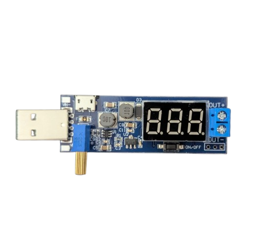
A step up converter, also known as a boost converter, is a DC-DC converter that increases the input voltage to a higher output voltage while maintaining power balance. This component is widely used in applications where a higher voltage is required from a lower voltage source, such as in battery-powered devices, renewable energy systems, and portable electronics.
Explore Projects Built with step up converter


Explore Projects Built with step up converter
Common Applications and Use Cases
- Powering high-voltage devices from low-voltage batteries
- Solar power systems to step up panel voltage
- LED drivers for high-power LEDs
- Electric vehicles and robotics
- Portable power banks and chargers
Technical Specifications
Below are the key technical details for the step up converter (Manufacturer: China, Part ID: Converter):
General Specifications
| Parameter | Value |
|---|---|
| Input Voltage Range | 3V to 32V |
| Output Voltage Range | 5V to 35V |
| Maximum Output Current | 2A (continuous), 3A (peak) |
| Efficiency | Up to 92% |
| Switching Frequency | 150 kHz |
| Operating Temperature | -40°C to +85°C |
| Dimensions | 43mm x 21mm x 14mm |
Pin Configuration and Descriptions
| Pin Name | Pin Number | Description |
|---|---|---|
| VIN | 1 | Positive input voltage terminal (3V to 32V). |
| GND | 2 | Ground terminal for input and output. |
| VOUT | 3 | Positive output voltage terminal (5V to 35V). |
| ADJ | 4 | Voltage adjustment pin (optional, for tuning). |
Usage Instructions
How to Use the Step Up Converter in a Circuit
- Connect the Input Voltage:
- Attach the positive terminal of your power source to the
VINpin. - Connect the negative terminal of your power source to the
GNDpin.
- Attach the positive terminal of your power source to the
- Connect the Output Load:
- Attach the positive terminal of your load to the
VOUTpin. - Connect the negative terminal of your load to the
GNDpin.
- Attach the positive terminal of your load to the
- Adjust the Output Voltage (if needed):
- Use a small screwdriver to turn the potentiometer on the module.
- Clockwise rotation increases the output voltage, while counterclockwise decreases it.
- Use a multimeter to monitor the output voltage during adjustment.
- Power On:
- Ensure all connections are secure and power on the input source.
Important Considerations and Best Practices
- Input Voltage: Ensure the input voltage is within the specified range (3V to 32V).
- Output Voltage: Do not exceed the maximum output voltage (35V) or current (3A peak).
- Heat Dissipation: For high-power applications, consider adding a heatsink or active cooling to prevent overheating.
- Polarity: Double-check the polarity of your connections to avoid damaging the module.
- Load Testing: Gradually increase the load to ensure stable operation and avoid overloading the converter.
Example: Using the Step Up Converter with an Arduino UNO
Below is an example of how to use the step up converter to power an Arduino UNO from a 3.7V Li-ion battery:
Circuit Connections
- Connect the positive terminal of the Li-ion battery to the
VINpin of the step up converter. - Connect the negative terminal of the battery to the
GNDpin of the converter. - Adjust the output voltage to 9V using the potentiometer.
- Connect the
VOUTpin of the converter to the Arduino UNO'sVINpin. - Connect the
GNDpin of the converter to the Arduino UNO'sGNDpin.
Sample Arduino Code
// Example code to blink an LED connected to pin 13 of the Arduino UNO
// Ensure the step up converter is providing 9V to the Arduino's VIN pin

void setup() {
  pinMode(13, OUTPUT); // Set pin 13 as an output pin
}

void loop() {
  digitalWrite(13, HIGH); // Turn the LED on
  delay(1000);            // Wait for 1 second
  digitalWrite(13, LOW);  // Turn the LED off
  delay(1000);            // Wait for 1 second
}
Troubleshooting and FAQs
Common Issues and Solutions
No Output Voltage:
- Check all connections for proper polarity and secure attachment.
- Verify that the input voltage is within the specified range.
- Ensure the potentiometer is not set to the minimum output voltage.
Overheating:
- Reduce the load current to within the rated limits.
- Add a heatsink or active cooling to the module.
Unstable Output Voltage:
- Check for loose connections or poor solder joints.
- Ensure the input voltage is stable and not fluctuating.
Output Voltage Not Adjustable:
- Verify that the potentiometer is functional and not damaged.
- Ensure the input voltage is higher than the minimum required for adjustment.
FAQs
Q: Can I use this step up converter to power a 12V device from a 5V USB source?
A: Yes, as long as the input current from the USB source is sufficient to meet the power requirements of the 12V device.
Q: What happens if I exceed the maximum output current?
A: Exceeding the maximum output current may cause the module to overheat, shut down, or become permanently damaged.
Q: Can I use this module with a solar panel?
A: Yes, but ensure the solar panel's output voltage and current are within the module's input range and power limits.
Q: Is the module protected against reverse polarity?
A: No, this module does not have reverse polarity protection. Always double-check your connections before powering on.