
How to Use STM 32F407 Discovery Kit: Examples, Pinouts, and Specs
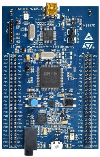
 Design with STM 32F407 Discovery Kit in Cirkit Designer
Introduction
The STM32F407 Discovery Kit is a development board manufactured by Microcontroller, featuring the STM32F4 series microcontroller (part ID: STM32F4). This board is designed to simplify prototyping and testing of embedded applications. It integrates the STM32F407 microcontroller, which is based on the ARM Cortex-M4 architecture, and includes a wide range of peripherals, sensors, and interfaces to support diverse development needs.
Explore Projects Built with STM 32F407 Discovery Kit
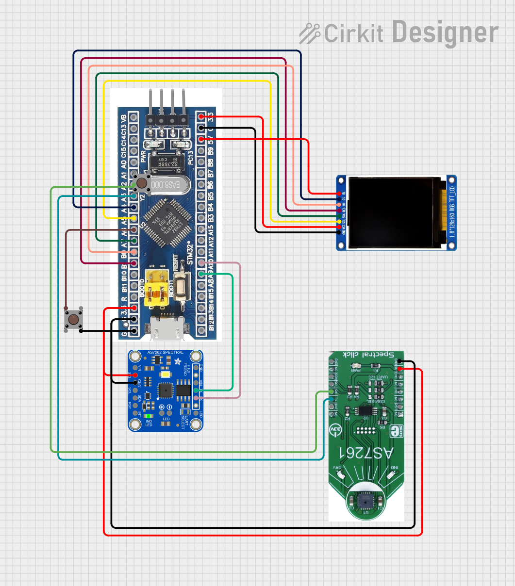 Open Project in Cirkit Designer
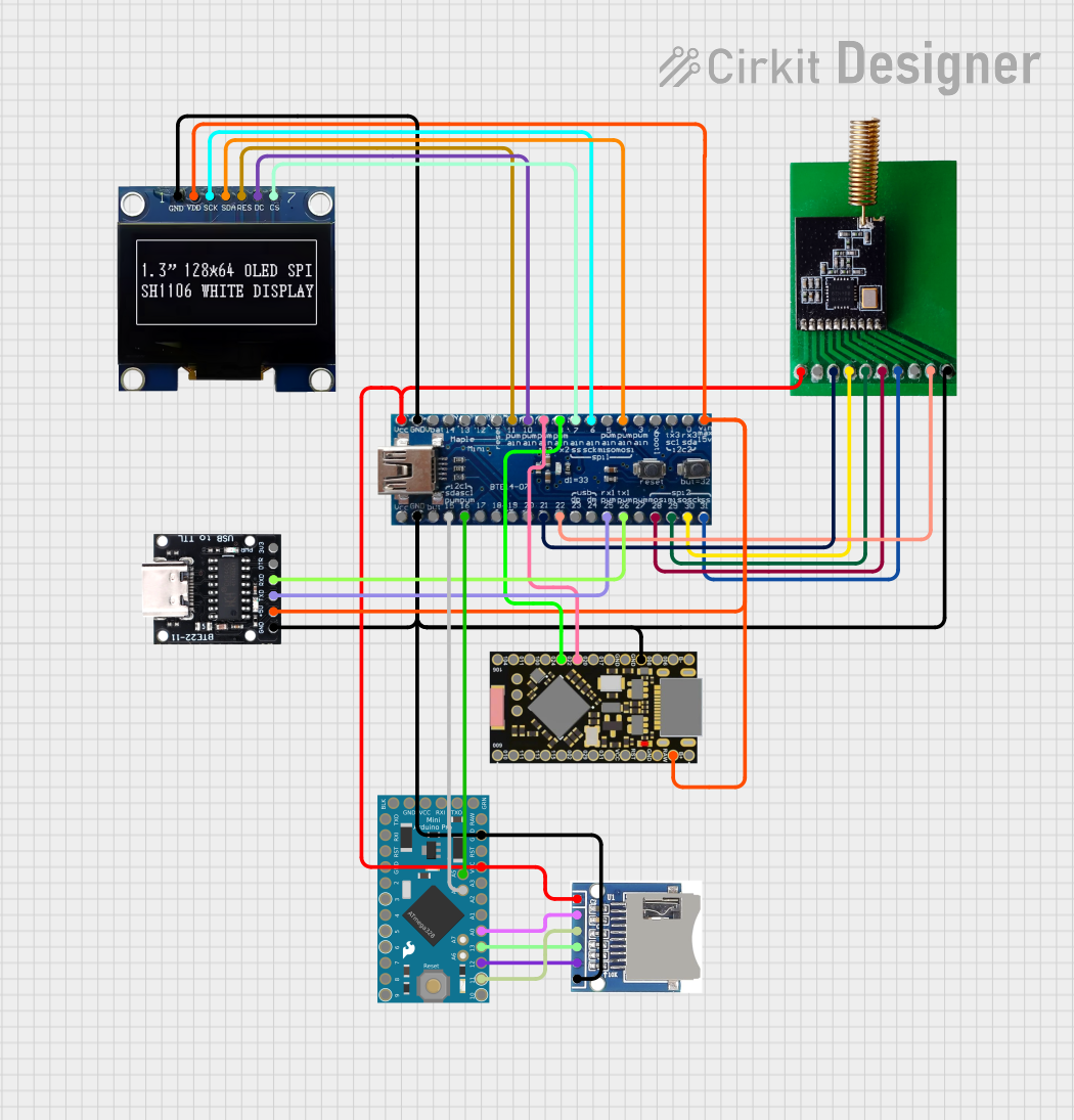 Open Project in Cirkit Designer
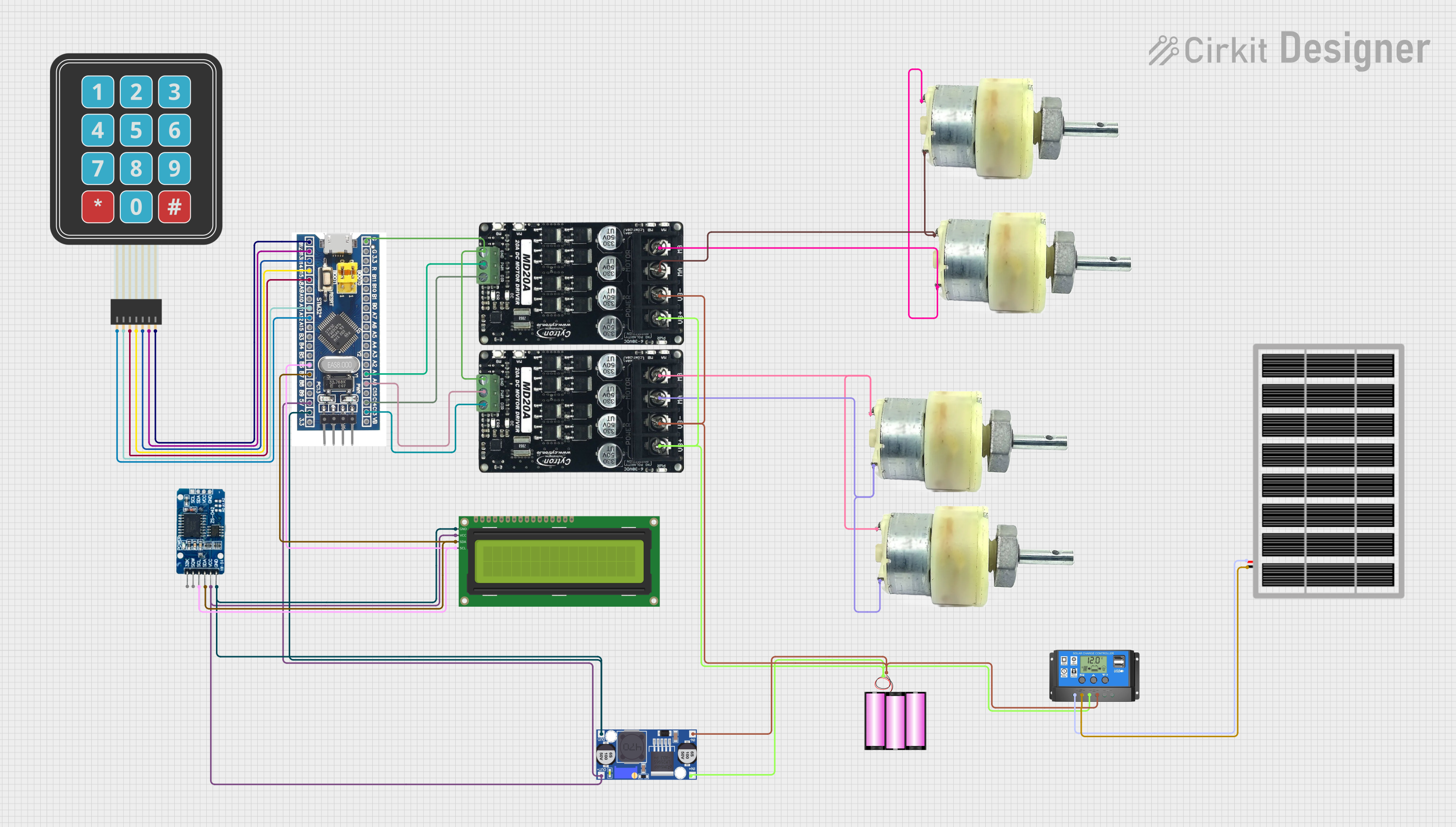 Open Project in Cirkit Designer
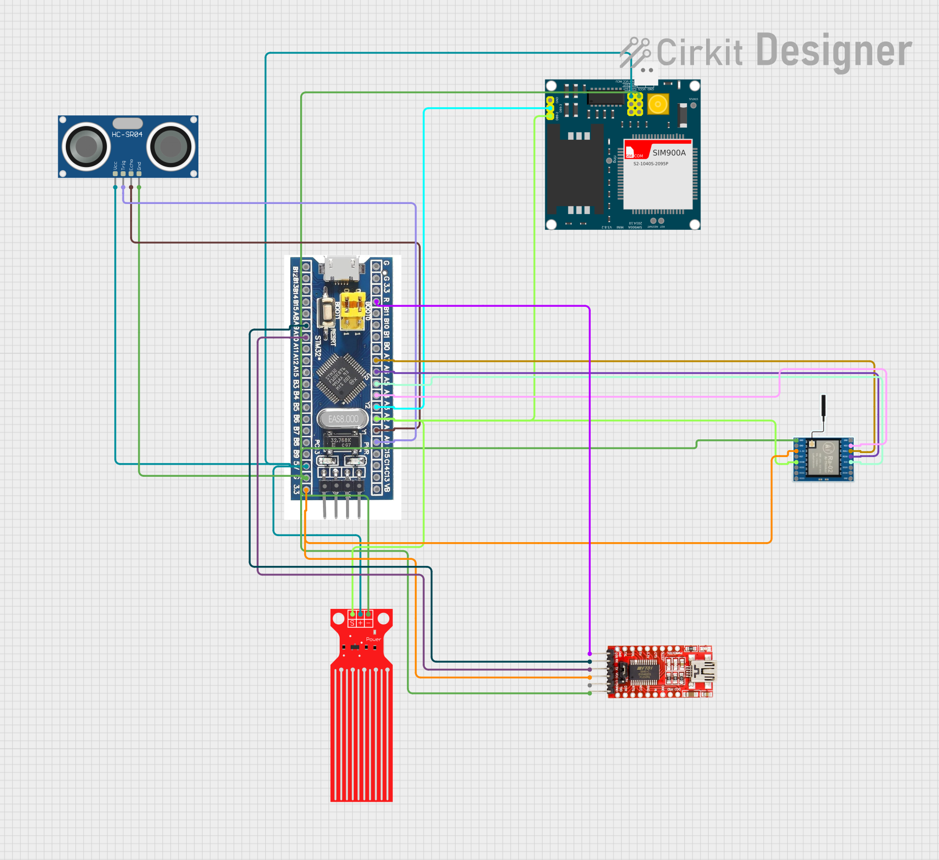 Open Project in Cirkit Designer
Explore Projects Built with STM 32F407 Discovery Kit
Open Project in Cirkit DesignerOpen Project in Cirkit DesignerOpen Project in Cirkit DesignerOpen Project in Cirkit DesignerCommon Applications and Use Cases
- Embedded systems development
- Prototyping IoT devices
- Motor control applications
- Audio processing and DSP applications
- Educational purposes for learning ARM Cortex-M4 programming
- Industrial automation and robotics
Technical Specifications
Key Technical Details
| Specification | Value |
|---|---|
| Microcontroller | STM32F407VGT6 (ARM Cortex-M4, 32-bit) |
| Operating Voltage | 3.3V |
| Clock Speed | Up to 168 MHz |
| Flash Memory | 1 MB |
| SRAM | 192 KB |
| GPIO Pins | 82 (multiplexed with peripherals) |
| Communication Interfaces | USART, SPI, I2C, CAN, USB OTG, Ethernet |
| Analog Inputs | 16 (12-bit ADC) |
| Timers | 17 (including advanced control timers) |
| Debugging Interface | ST-LINK/V2 (onboard) |
| Power Supply | USB or external (5V) |
| Dimensions | 100 mm x 65 mm |
Pin Configuration and Descriptions
The STM32F407 Discovery Kit features multiple headers for GPIO and peripheral connections. Below is a summary of the key pin configurations:
GPIO Header Pinout
| Pin Number | Pin Name | Functionality | Notes |
|---|---|---|---|
| 1 | VDD | 3.3V Power Supply | Power output for peripherals |
| 2 | GND | Ground | Common ground |
| 3 | PA0 | GPIO/ADC Input | Multiplexed with ADC_IN0 |
| 4 | PA1 | GPIO/ADC Input | Multiplexed with ADC_IN1 |
| 5 | PB6 | GPIO/I2C1_SCL | I2C1 Clock Line |
| 6 | PB7 | GPIO/I2C1_SDA | I2C1 Data Line |
| 7 | PC13 | GPIO/User Button Input | Connected to onboard button |
| 8 | PA9 | GPIO/USART1_TX | UART Transmit |
| 9 | PA10 | GPIO/USART1_RX | UART Receive |
| 10 | PC0 | GPIO/ADC Input | Multiplexed with ADC_IN10 |
Power and Debugging Pins
| Pin Name | Functionality | Notes |
|---|---|---|
| 5V | External Power Input | Accepts 5V input |
| 3.3V | Regulated Power Output | For powering external devices |
| GND | Ground | Common ground |
| SWDIO | Debugging Interface (SWD Data) | Used for programming/debugging |
| SWCLK | Debugging Interface (SWD Clock) | Used for programming/debugging |
Usage Instructions
How to Use the STM32F407 Discovery Kit in a Circuit
Powering the Board:
- Connect the board to your computer via the onboard micro-USB connector for power and programming.
- Alternatively, supply 5V to the external power input pin.
Programming the Microcontroller:
- Use the onboard ST-LINK/V2 debugger to program the STM32F407 microcontroller.
- Compatible IDEs include STM32CubeIDE, Keil uVision, and IAR Embedded Workbench.
Connecting Peripherals:
- Use the GPIO headers to connect external sensors, actuators, or other devices.
- Ensure that the voltage levels of connected peripherals are compatible with the 3.3V logic level of the STM32F407.
Using Communication Interfaces:
- Configure USART, SPI, I2C, or CAN interfaces in your firmware to communicate with external devices.
- Refer to the STM32F407 datasheet for detailed configuration options.
Using the Onboard Peripherals:
- The board includes an onboard accelerometer, LEDs, and a user button. These can be accessed directly in your firmware.
Important Considerations and Best Practices
- Voltage Levels: Ensure all connected peripherals operate at 3.3V logic levels to avoid damaging the microcontroller.
- Clock Configuration: Properly configure the system clock in your firmware to achieve the desired performance.
- Debugging: Use the ST-LINK/V2 interface for debugging and troubleshooting your code.
- Static Protection: Handle the board with care to avoid damage from electrostatic discharge (ESD).
Example Code for Arduino IDE (Using STM32 Core)
The STM32F407 Discovery Kit can be programmed using the Arduino IDE with the STM32 core installed. Below is an example of blinking the onboard LED:
// Example: Blink onboard LED (connected to pin PD12)

// Define the onboard LED pin
#define LED_PIN PD12

void setup() {
  pinMode(LED_PIN, OUTPUT); // Set LED pin as output
}

void loop() {
  digitalWrite(LED_PIN, HIGH); // Turn LED on
  delay(500);                  // Wait for 500 ms
  digitalWrite(LED_PIN, LOW);  // Turn LED off
  delay(500);                  // Wait for 500 ms
}
Troubleshooting and FAQs
Common Issues and Solutions
Board Not Detected by Computer:
- Ensure the USB cable is functional and properly connected.
- Verify that the ST-LINK drivers are installed on your computer.
Program Not Running After Upload:
- Check the power supply to the board.
- Ensure the correct clock configuration in your firmware.
GPIO Pins Not Responding:
- Verify the pin mode configuration in your code.
- Check for short circuits or incorrect connections.
Debugging Interface Not Working:
- Ensure the SWDIO and SWCLK pins are not being used for other purposes.
- Verify the ST-LINK firmware is up to date.
FAQs
Q: Can I power the board using a battery?
A: Yes, you can power the board using a 5V battery connected to the external power input pin.
Q: Is the STM32F407 Discovery Kit compatible with Arduino libraries?
A: Yes, with the STM32 core installed in the Arduino IDE, you can use many Arduino libraries.
Q: How do I reset the board?
A: Press the onboard reset button to restart the microcontroller.
Q: Can I use the board for audio processing?
A: Yes, the STM32F407 microcontroller includes a floating-point unit (FPU) and DSP instructions, making it suitable for audio processing applications.