How to Use 2S 7.4V 8A Li-ion 18650 Lithium Battery Charger Protection Board: Examples, Pinouts, and Specs
2S 7.4V 8A Li-ion 18650 Lithium Battery Charger Protection Board Documentation
1. Introduction
The 2S 7.4V 8A Li-ion 18650 Lithium Battery Charger Protection Board is a compact and efficient module designed to manage and protect two 18650 lithium-ion cells connected in series. This protection board ensures the safe operation of the battery pack by providing essential features such as overcharge protection, over-discharge protection, and short-circuit protection. It is ideal for applications requiring a reliable power source with a maximum output current of 8A.
Common Applications:
- Power banks
- Portable electronic devices
- DIY battery packs
- Robotics and automation systems
- LED lighting systems
- RC toys and drones
This protection board is a critical component for ensuring the longevity and safety of lithium-ion batteries in various applications.
2. Technical Specifications
The following table outlines the key technical details of the 2S 7.4V 8A Li-ion 18650 Lithium Battery Charger Protection Board:
| Parameter | Specification |
|---|---|
| Battery Configuration | 2S (Two 18650 cells in series) |
| Input Voltage Range | 7.4V to 8.4V |
| Overcharge Protection | 4.25V ± 0.05V per cell |
| Over-discharge Protection | 2.5V ± 0.1V per cell |
| Maximum Output Current | 8A |
| Continuous Discharge Current | 6A |
| Short-circuit Protection | Yes |
| Board Dimensions | ~45mm x 15mm x 3mm |
| Operating Temperature | -20°C to 60°C |
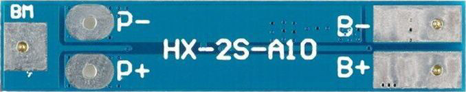
Pin Configuration and Descriptions
| Pin Name | Description |
|---|---|
| B+ | Positive terminal of the battery pack (connect to the positive terminal of the first cell). |
| B- | Negative terminal of the battery pack (connect to the negative terminal of the second cell). |
| P+ | Positive output terminal (connect to the load or charging circuit). |
| P- | Negative output terminal (connect to the load or charging circuit). |
3. Usage Instructions
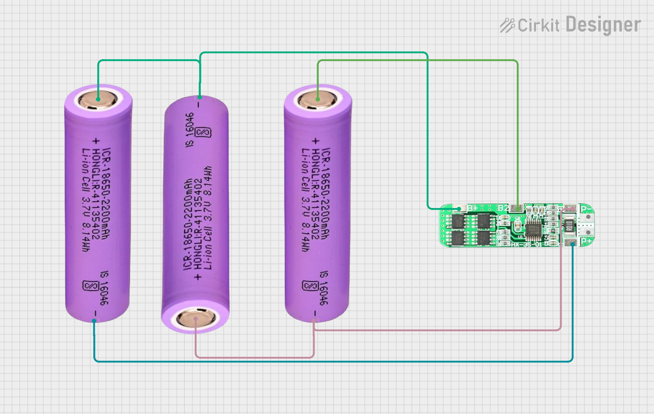
Connecting the Protection Board:
Prepare the Battery Pack:
- Ensure you have two 18650 lithium-ion cells connected in series. The total voltage should be between 7.4V and 8.4V.
- Verify the polarity of the cells before connecting them to the protection board.
Connect the Battery Pack to the Board:
- Connect the positive terminal of the battery pack to the B+ pin.
- Connect the negative terminal of the battery pack to the B- pin.
Connect the Load or Charger:
- Connect the positive terminal of the load or charger to the P+ pin.
- Connect the negative terminal of the load or charger to the P- pin.
Verify Connections:
- Double-check all connections to ensure proper polarity and secure wiring.
Important Considerations:
- Avoid Reverse Polarity: Connecting the battery or load with reversed polarity can damage the protection board.
- Use Compatible Batteries: Only use 18650 lithium-ion cells with matching capacities and charge levels.
- Heat Dissipation: Ensure adequate ventilation or heat dissipation if the board operates near its maximum current rating.
- Charging Voltage: Use a charger with an output voltage of 8.4V for optimal charging.
4. Example Application with Arduino UNO
The 2S 7.4V protection board can be used to power an Arduino UNO in portable projects. Below is an example of how to connect the board to an Arduino UNO and monitor the battery voltage.
Circuit Diagram:
- Connect the P+ and P- terminals of the protection board to the Arduino's Vin and GND pins, respectively.
- Use a voltage divider circuit to measure the battery voltage with the Arduino's analog input pin.
Arduino Code Example:
// Example code to monitor battery voltage using Arduino UNO
// Ensure the voltage divider reduces the battery voltage to below 5V for safe ADC input

const int voltagePin = A0; // Analog pin connected to the voltage divider
const float voltageDividerRatio = 5.7; // Adjust based on your resistor values
const float referenceVoltage = 5.0; // Arduino's ADC reference voltage (5V)

void setup() {
  Serial.begin(9600); // Initialize serial communication
  pinMode(voltagePin, INPUT); // Set the voltage pin as input
}

void loop() {
  int rawADC = analogRead(voltagePin); // Read the raw ADC value
  float batteryVoltage = (rawADC * referenceVoltage / 1023.0) * voltageDividerRatio;

  // Print the battery voltage to the Serial Monitor
  Serial.print("Battery Voltage: ");
  Serial.print(batteryVoltage);
  Serial.println(" V");

  delay(1000); // Wait for 1 second before the next reading
}
Notes:
- Use resistors in the voltage divider circuit to scale the battery voltage to a safe level for the Arduino's analog input (below 5V).
- Adjust the
voltageDividerRatioin the code based on the resistor values used in the voltage divider.
5. Troubleshooting and FAQs
Common Issues and Solutions:
| Issue | Possible Cause | Solution |
|---|---|---|
| Board does not output voltage | Incorrect wiring or reversed polarity | Verify all connections and ensure correct polarity. |
| Overheating during operation | Exceeding the maximum current rating | Reduce the load current or improve heat dissipation. |
| Battery pack not charging | Charger voltage too low or disconnected | Ensure the charger provides 8.4V and is properly connected to P+ and P-. |
| Short-circuit protection triggered | Load is drawing excessive current | Check the load for faults or reduce the load current. |
Frequently Asked Questions:
Can I use this board with a single 18650 cell?
- No, this board is designed specifically for two 18650 cells connected in series (2S configuration).
What happens if the battery voltage drops below 2.5V per cell?
- The board will activate over-discharge protection and disconnect the load to prevent battery damage.
Can I use this board for applications requiring more than 8A?
- No, the maximum output current is 8A. Exceeding this limit may damage the board or trigger short-circuit protection.
Is the board compatible with other lithium-ion battery types?
- The board is optimized for 18650 cells. It may work with other lithium-ion batteries, but compatibility is not guaranteed.
This documentation provides a comprehensive guide to using the 2S 7.4V 8A Li-ion 18650 Lithium Battery Charger Protection Board effectively and safely. For further assistance, consult the manufacturer’s datasheet or contact technical support.
Explore Projects Built with 2S 7.4V 8A Li-ion 18650 Lithium Battery Charger Protection Board


Explore Projects Built with 2S 7.4V 8A Li-ion 18650 Lithium Battery Charger Protection Board