Cirkit Designer Logo
Cirkit Designer
Your all-in-one circuit design IDE
Home / 
Component Documentation

How to Use P6KE6.8A: Examples, Pinouts, and Specs

Image of P6KE6.8A
Cirkit Designer LogoDesign with P6KE6.8A in Cirkit Designer

Introduction

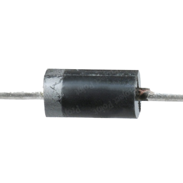
The P6KE6.8A is a Transient Voltage Suppressor (TVS) diode designed to protect sensitive electronic equipment from voltage spikes and transients. By shunting excess current, it prevents damage to the circuit due to electrostatic discharge, electrical fast transients, and effects of secondary lightning. Common applications include:

  • Power supply protection
  • Automotive systems
  • Data line protection
  • Industrial electronics

Explore Projects Built with P6KE6.8A

Use Cirkit Designer to design, explore, and prototype these projects online. Some projects support real-time simulation. Click "Open Project" to start designing instantly!
Battery-Powered Emergency Alert System with NUCLEO-F072RB, SIM800L, and GPS NEO 6M
Image of women safety: A project utilizing P6KE6.8A in a practical application
This circuit is an emergency alert system that uses a NUCLEO-F072RB microcontroller to send SMS alerts and make calls via a SIM800L GSM module, while obtaining location data from a GPS NEO 6M module. The system is powered by a Li-ion battery and includes a TP4056 module for battery charging and protection, with a rocker switch to control power to the microcontroller.
Cirkit Designer LogoOpen Project in Cirkit Designer
Aircraft Tow Release Control System with Dual Battery Backup
Image of Queen Air Tow Release Wiring: A project utilizing P6KE6.8A in a practical application
This circuit is designed for a tow release control system in an aircraft, featuring a P68 Tow Control Panel and a Tow Release With Switches assembly. The control panel receives power from two separate aircraft batteries, with one providing main power and the other serving as a backup. The Tow Release With Switches assembly is connected to the control panel, allowing for the actuation of the tow mechanism and providing feedback via an LED indicator.
Cirkit Designer LogoOpen Project in Cirkit Designer
KRYPTON-6xSTG Signal Processing Circuit
Image of Industrijski seminar: A project utilizing P6KE6.8A in a practical application
The circuit consists of two KRYPTON-6xSTG components connected in series, where the 'OUT' pin of the first component is connected to the 'IN' pin of the second component. This setup suggests a signal or data flow from the first KRYPTON-6xSTG to the second.
Cirkit Designer LogoOpen Project in Cirkit Designer
Bluetooth Audio Receiver with Battery-Powered Amplifier and Loudspeakers
Image of speaker bluetooh portable: A project utilizing P6KE6.8A in a practical application
This circuit is a Bluetooth-enabled audio system powered by a rechargeable 18650 Li-ion battery. It includes a TP4056 module for battery charging and protection, a PAM8403 amplifier with volume control to drive two loudspeakers, and a Bluetooth audio receiver to wirelessly receive audio signals.
Cirkit Designer LogoOpen Project in Cirkit Designer

Explore Projects Built with P6KE6.8A

Use Cirkit Designer to design, explore, and prototype these projects online. Some projects support real-time simulation. Click "Open Project" to start designing instantly!
Image of women safety: A project utilizing P6KE6.8A in a practical application
Battery-Powered Emergency Alert System with NUCLEO-F072RB, SIM800L, and GPS NEO 6M
This circuit is an emergency alert system that uses a NUCLEO-F072RB microcontroller to send SMS alerts and make calls via a SIM800L GSM module, while obtaining location data from a GPS NEO 6M module. The system is powered by a Li-ion battery and includes a TP4056 module for battery charging and protection, with a rocker switch to control power to the microcontroller.
Cirkit Designer LogoOpen Project in Cirkit Designer
Image of Queen Air Tow Release Wiring: A project utilizing P6KE6.8A in a practical application
Aircraft Tow Release Control System with Dual Battery Backup
This circuit is designed for a tow release control system in an aircraft, featuring a P68 Tow Control Panel and a Tow Release With Switches assembly. The control panel receives power from two separate aircraft batteries, with one providing main power and the other serving as a backup. The Tow Release With Switches assembly is connected to the control panel, allowing for the actuation of the tow mechanism and providing feedback via an LED indicator.
Cirkit Designer LogoOpen Project in Cirkit Designer
Image of Industrijski seminar: A project utilizing P6KE6.8A in a practical application
KRYPTON-6xSTG Signal Processing Circuit
The circuit consists of two KRYPTON-6xSTG components connected in series, where the 'OUT' pin of the first component is connected to the 'IN' pin of the second component. This setup suggests a signal or data flow from the first KRYPTON-6xSTG to the second.
Cirkit Designer LogoOpen Project in Cirkit Designer
Image of speaker bluetooh portable: A project utilizing P6KE6.8A in a practical application
Bluetooth Audio Receiver with Battery-Powered Amplifier and Loudspeakers
This circuit is a Bluetooth-enabled audio system powered by a rechargeable 18650 Li-ion battery. It includes a TP4056 module for battery charging and protection, a PAM8403 amplifier with volume control to drive two loudspeakers, and a Bluetooth audio receiver to wirelessly receive audio signals.
Cirkit Designer LogoOpen Project in Cirkit Designer

Technical Specifications

Key Technical Details

  • Reverse Standoff Voltage (V_RWM): 5.8V
  • Breakdown Voltage (V_BR): 6.45V to 7.14V
  • Peak Pulse Power Dissipation (P_PP): 600W (10/1000μs waveform)
  • Clamping Voltage (V_C) at I_PP: 10.5V (I_PP = 57A)
  • Peak Pulse Current (I_PP): 57A (10/1000μs waveform)
  • Operating Junction Temperature: -55°C to +175°C

Pin Configuration and Descriptions

Pin Number Name Description
1 Anode Connects to the line to be protected
2 Cathode Connects to the ground or negative side of the circuit

Usage Instructions

How to Use the P6KE6.8A in a Circuit

  1. Identify the Line to Protect: Determine the line which is susceptible to voltage spikes.
  2. Circuit Placement: Connect the anode of the P6KE6.8A to the line and the cathode to the ground.
  3. Orientation: Ensure correct polarity by connecting the anode and cathode to the appropriate points in the circuit.

Important Considerations and Best Practices

  • Selecting the Right TVS: Ensure the reverse standoff voltage is slightly above the normal operating voltage.
  • Placement: Position the TVS diode as close as possible to the potential source of the transients.
  • Circuit Design: Use a low impedance path for the diode to ensure effective shunting of the transient current.
  • Thermal Considerations: Ensure proper heat dissipation to prevent overheating during surge events.

Troubleshooting and FAQs

Common Issues

  • Diode Not Functioning: Ensure the diode is not installed backward. The anode should be towards the line and the cathode towards the ground.
  • Circuit Damage After Surge: Check if the surge energy exceeded the diode's maximum rating. Replace with a diode with a higher power rating if necessary.

Solutions and Tips

  • Testing the Diode: Use a multimeter in diode mode to check for continuity. A good diode should show low resistance in one direction and high resistance in the reverse.
  • Surge Energy Calculation: Estimate the potential surge energy to select a diode with an appropriate power rating.

FAQs

Q: Can the P6KE6.8A be used for AC applications? A: Yes, it can be used in AC applications by placing two diodes in series with opposing polarities.

Q: What happens if the P6KE6.8A is exposed to a voltage higher than its breakdown voltage? A: The diode will go into avalanche mode and start conducting to clamp the voltage, protecting the circuit.

Q: How do I know if the P6KE6.8A is still functional after a surge event? A: Test the diode with a multimeter. If it shows a short or an open circuit, it may have been damaged and should be replaced.

Example Code for Arduino UNO

If you're using the P6KE6.8A to protect an Arduino UNO input, here's a simple example code snippet to read the voltage level:

int inputPin = A0; // Select the input pin for the voltage
int inputValue = 0; // Variable to store the value coming from the sensor

void setup() {
  Serial.begin(9600); // Initialize serial communication at 9600 bits per second
}

void loop() {
  inputValue = analogRead(inputPin); // Read the value from the sensor
  Serial.println(inputValue); // Print the value to the serial monitor
  delay(1000); // Wait for a second between readings
}

Note: This code assumes that the P6KE6.8A is properly installed to protect the analog input from voltage spikes. The Arduino itself has limited protection capabilities, so external protection like the P6KE6.8A is recommended for harsh environments.