
How to Use 20mm 8x8 dot matrix row cathode led display with narrow pcb pads: Examples, Pinouts, and Specs
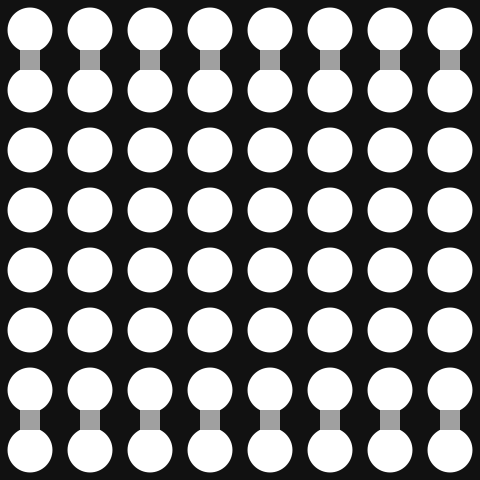
 Design with 20mm 8x8 dot matrix row cathode led display with narrow pcb pads in Cirkit Designer
Introduction
The 20mm 8x8 Dot Matrix Row Cathode LED Display is a compact and versatile module featuring an 8x8 grid of light-emitting diodes (LEDs) arranged in a matrix format. This row cathode design simplifies the control of individual LEDs, making it ideal for displaying characters, symbols, or custom patterns. Its narrow PCB pads ensure easy soldering and seamless integration into a wide range of electronic projects.
Explore Projects Built with 20mm 8x8 dot matrix row cathode led display with narrow pcb pads
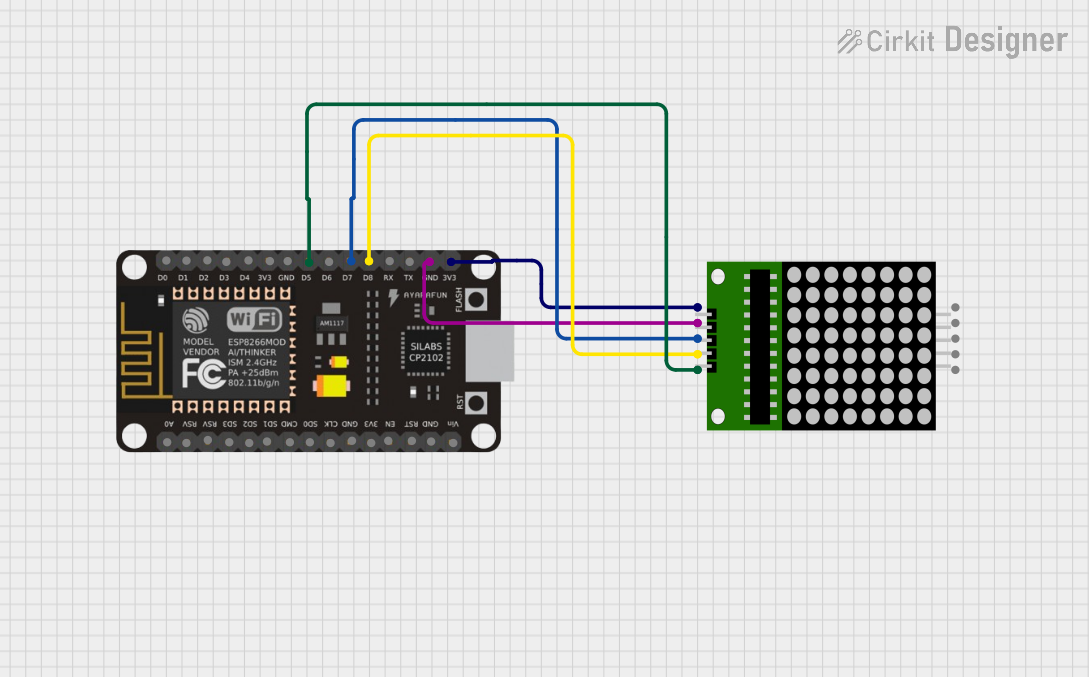 Open Project in Cirkit Designer
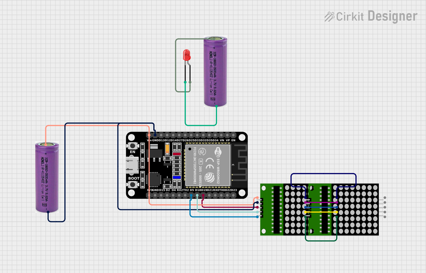 Open Project in Cirkit Designer
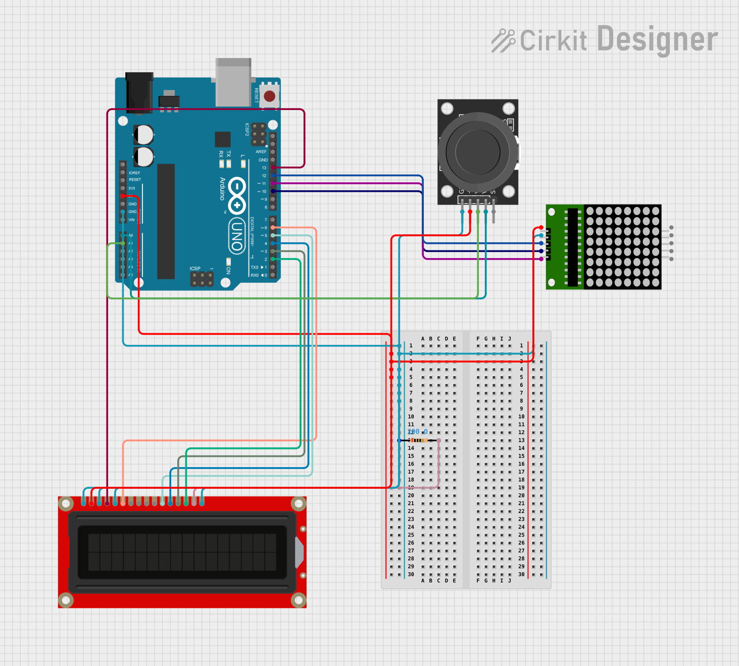 Open Project in Cirkit Designer
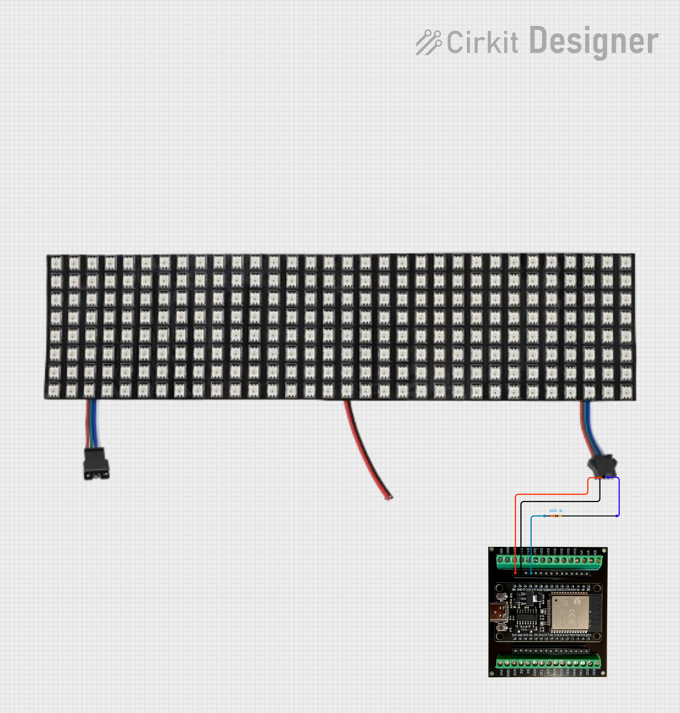 Open Project in Cirkit Designer
Explore Projects Built with 20mm 8x8 dot matrix row cathode led display with narrow pcb pads
Open Project in Cirkit DesignerOpen Project in Cirkit DesignerOpen Project in Cirkit DesignerOpen Project in Cirkit DesignerCommon Applications and Use Cases
- Digital clocks and timers
- Scrolling text displays
- Custom animations and patterns
- Status indicators for embedded systems
- Educational projects and prototyping
Technical Specifications
Below are the key technical details and pin configuration for the 20mm 8x8 Dot Matrix Row Cathode LED Display:
Key Technical Details
| Parameter | Specification |
|---|---|
| LED Matrix Size | 8x8 (64 LEDs) |
| Module Dimensions | 20mm x 20mm |
| LED Color | Red (or other variants, if specified) |
| Forward Voltage (per LED) | 1.8V to 2.2V |
| Forward Current (per LED) | 10mA to 20mA |
| Matrix Type | Row Cathode |
| PCB Pad Type | Narrow for easy soldering |
Pin Configuration and Descriptions
The module has 16 pins, with 8 pins corresponding to rows (cathodes) and 8 pins corresponding to columns (anodes). The pinout is as follows:
| Pin Number | Description | Function |
|---|---|---|
| 1 | Row 1 Cathode | Controls LEDs in Row 1 |
| 2 | Row 2 Cathode | Controls LEDs in Row 2 |
| 3 | Row 3 Cathode | Controls LEDs in Row 3 |
| 4 | Row 4 Cathode | Controls LEDs in Row 4 |
| 5 | Row 5 Cathode | Controls LEDs in Row 5 |
| 6 | Row 6 Cathode | Controls LEDs in Row 6 |
| 7 | Row 7 Cathode | Controls LEDs in Row 7 |
| 8 | Row 8 Cathode | Controls LEDs in Row 8 |
| 9 | Column 1 Anode | Controls LEDs in Column 1 |
| 10 | Column 2 Anode | Controls LEDs in Column 2 |
| 11 | Column 3 Anode | Controls LEDs in Column 3 |
| 12 | Column 4 Anode | Controls LEDs in Column 4 |
| 13 | Column 5 Anode | Controls LEDs in Column 5 |
| 14 | Column 6 Anode | Controls LEDs in Column 6 |
| 15 | Column 7 Anode | Controls LEDs in Column 7 |
| 16 | Column 8 Anode | Controls LEDs in Column 8 |
Usage Instructions
How to Use the Component in a Circuit
- Power Requirements: Ensure that the forward voltage and current ratings of the LEDs are not exceeded. Use current-limiting resistors (typically 220Ω to 330Ω) in series with the anodes or cathodes to protect the LEDs.
- Matrix Control: Use a microcontroller (e.g., Arduino UNO) or a dedicated LED driver IC (e.g., MAX7219) to control the matrix. The rows and columns are multiplexed, meaning only one row or column is active at a time.
- Wiring: Connect the row cathodes and column anodes to the microcontroller or driver IC. Ensure proper grounding and power supply connections.
Important Considerations and Best Practices
- Multiplexing: To display patterns or characters, implement a multiplexing technique where rows or columns are activated sequentially at high speed. This creates the illusion of a steady display.
- Resistors: Always use appropriate resistors to limit current through the LEDs.
- Heat Management: Avoid driving all LEDs at maximum brightness for extended periods to prevent overheating.
- Soldering: The narrow PCB pads are designed for easy soldering. Use a fine-tipped soldering iron and avoid excessive heat to prevent damage.
Example Code for Arduino UNO
Below is an example of how to control the 8x8 dot matrix using an Arduino UNO. This example lights up a diagonal pattern on the display:
// Define row and column pins
const int rowPins[8] = {2, 3, 4, 5, 6, 7, 8, 9}; // Row cathodes
const int colPins[8] = {10, 11, 12, 13, A0, A1, A2, A3}; // Column anodes

void setup() {
  // Set all row and column pins as outputs
  for (int i = 0; i < 8; i++) {
    pinMode(rowPins[i], OUTPUT);
    pinMode(colPins[i], OUTPUT);
  }
}

void loop() {
  // Light up a diagonal pattern
  for (int i = 0; i < 8; i++) {
    // Turn on the current row
    digitalWrite(rowPins[i], LOW); // Row cathodes are active LOW
    // Turn on the corresponding column
    digitalWrite(colPins[i], HIGH); // Column anodes are active HIGH
    delay(200); // Keep the LED on for 200ms
    // Turn off the current row and column
    digitalWrite(rowPins[i], HIGH);
    digitalWrite(colPins[i], LOW);
  }
}
Notes on the Code
- The rows are active LOW, meaning they are turned on by setting the pin to
LOW. - The columns are active HIGH, meaning they are turned on by setting the pin to
HIGH. - Adjust the
delay()value to control the speed of the pattern.
Troubleshooting and FAQs
Common Issues and Solutions
No LEDs Lighting Up:
- Check the power supply and ensure proper connections.
- Verify that current-limiting resistors are in place.
- Ensure the microcontroller pins are correctly configured as outputs.
Dim or Flickering LEDs:
- Ensure the multiplexing frequency is high enough (e.g., >100Hz) to avoid visible flicker.
- Check for loose connections or insufficient power supply.
Overheating:
- Reduce the current through the LEDs by increasing the resistor value.
- Avoid driving all LEDs at maximum brightness simultaneously.
Incorrect Patterns Displayed:
- Double-check the wiring of rows and columns.
- Verify the logic in your code to ensure proper row-column activation.
FAQs
Q: Can I use this module with a MAX7219 driver IC?
A: Yes, the MAX7219 is a popular choice for controlling 8x8 LED matrices. It simplifies wiring and multiplexing.
Q: What is the recommended resistor value for this module?
A: Typically, 220Ω to 330Ω resistors are used to limit the current through each LED.
Q: Can I use this module with a 3.3V microcontroller?
A: Yes, but ensure the forward voltage of the LEDs is compatible, and adjust resistor values accordingly.
Q: How do I display characters or text?
A: Use a character library or create a custom lookup table to map characters to row-column patterns.
This documentation provides a comprehensive guide to using the 20mm 8x8 Dot Matrix Row Cathode LED Display. With proper setup and control, this module can bring dynamic visual elements to your projects!