How to Use Teensy 4.1: Examples, Pinouts, and Specs
Introduction
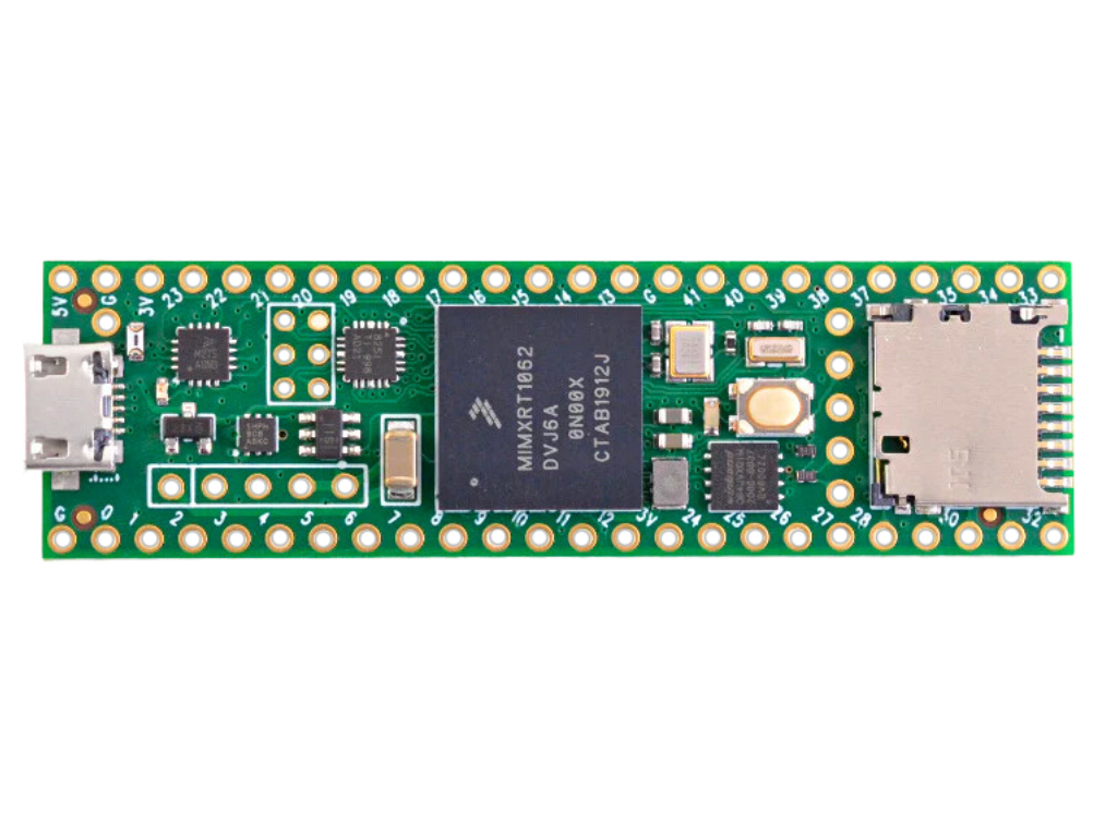
The Teensy 4.1 is a high-performance microcontroller development board designed and manufactured by PJRC, often used in the Arduino ecosystem. It is based on the 32-bit ARM Cortex-M7 processor, which provides a significant step up in performance compared to traditional 8-bit microcontrollers. This makes the Teensy 4.1 an excellent choice for advanced projects that require intensive processing power, such as digital audio processing, real-time data analysis, and complex control systems.
Common applications for the Teensy 4.1 include:
- Musical instruments and synthesizers
- Advanced robotics
- Home automation systems
- High-speed USB communication
- Prototyping Internet of Things (IoT) devices
Explore Projects Built with Teensy 4.1
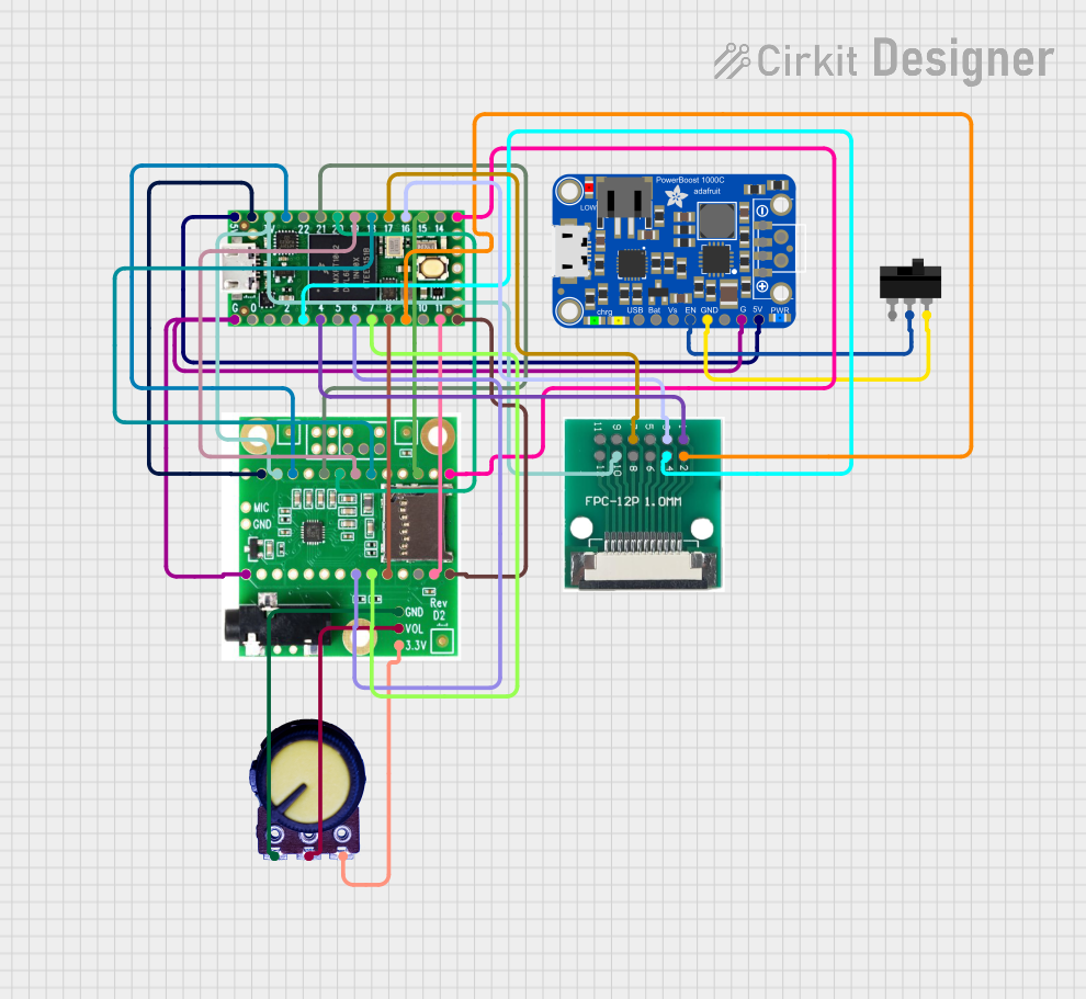
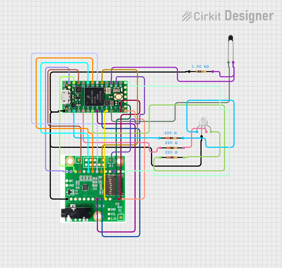
Explore Projects Built with Teensy 4.1
Technical Specifications
Key Technical Details
- Processor: ARM Cortex-M7 at 600 MHz
- Flash Memory: 8 MB (64 Mbit)
- RAM: 1 MB
- Voltage (Input): 3.3V to 5V
- Digital I/O Pins: 40 (including 31 PWM capable)
- Analog Inputs: 14 (18-bit ADC)
- Analog Outputs: 2 (12-bit DAC)
- Serial Ports: 7
- I2C Ports: 3
- SPI Ports: 1
- CAN Bus Ports: 2
- USB Host/Device: 1
- Ethernet: 10/100 Mbit (6 pins)
- SD Card Slot: 1 (SDIO capable)
Pin Configuration and Descriptions
| Pin Number | Function | Description |
|---|---|---|
| 0-33 | Digital I/O | General-purpose input/output pins |
| 34-39 | Digital I/O | Digital pins with PWM capability |
| A0-A13 | Analog Input | Analog input pins with 18-bit ADC |
| DAC0, DAC1 | Analog Output | Analog output pins with 12-bit DAC |
| 40-41 | CAN Bus | CAN communication pins |
| 42-47 | Ethernet | Pins for Ethernet communication |
| 48-53 | USB Host | Pins for USB host/device functionality |
| SD | SD Card Slot | Dedicated pins for SD card communication |
Usage Instructions
Integrating Teensy 4.1 into a Circuit
To use the Teensy 4.1 in a circuit:
- Powering the Board: Connect a 3.3V to 5V power supply to the VIN pin and GND.
- Programming: Connect the board to a computer using a micro USB cable to upload sketches.
- Digital I/O: Use the digital pins for input or output by setting their mode in the code.
- Analog Input: Connect sensors to the analog pins to read varying voltages.
- Analog Output: Use the DAC pins to output analog signals.
- Communication: Utilize the serial, I2C, SPI, CAN, or Ethernet pins for communication with other devices.
Important Considerations and Best Practices
- Always ensure that the power supply voltage is within the specified range to avoid damaging the board.
- When connecting external components, make sure they are compatible with the board's logic level (3.3V).
- Use proper decoupling capacitors close to the board's power pins to minimize power supply noise.
- Avoid drawing more than 250 mA from the 3.3V onboard regulator.
- For high-speed USB communication, ensure that the USB cable is of good quality and as short as possible.
Troubleshooting and FAQs
Common Issues
- Board Not Recognized: Ensure the micro USB cable is properly connected and the computer's USB port is functioning.
- Sketch Not Uploading: Check the selected board and port in the Arduino IDE. Press the reset button on the board and try again.
- Unexpected Behavior: Verify that all connections are secure and that the code uploaded to the board is correct.
Solutions and Tips
- If the board is not recognized, try a different USB cable or port.
- For upload issues, ensure that the correct drivers are installed and that the Teensy Loader application is running.
- Review the code for errors and ensure that the correct libraries are included.
FAQs
Q: Can I power the Teensy 4.1 with a battery? A: Yes, you can power the Teensy 4.1 with a battery as long as the voltage is within the 3.3V to 5V range.
Q: Is the Teensy 4.1 compatible with all Arduino libraries? A: While many Arduino libraries are compatible, some may need modifications due to the different processor architecture.
Q: How do I use the Ethernet capabilities of the Teensy 4.1? A: To use Ethernet, you will need to solder an Ethernet PHY to the provided pins and use the appropriate library for communication.
Example Code for Arduino UNO
The following is a simple example of blinking an LED connected to pin 13 on the Teensy 4.1. This code is compatible with the Arduino IDE.
// Blink an LED connected to pin 13

void setup() {
  pinMode(13, OUTPUT); // Set pin 13 as an output
}

void loop() {
  digitalWrite(13, HIGH);   // Turn the LED on
  delay(1000);              // Wait for a second
  digitalWrite(13, LOW);    // Turn the LED off
  delay(1000);              // Wait for a second
}
Remember to select the correct board (Teensy 4.1) in the Arduino IDE before uploading the code.