Cirkit Designer Logo
Cirkit Designer
Your all-in-one circuit design IDE
Home / 
Component Documentation

How to Use TC7660: Examples, Pinouts, and Specs

Image of TC7660
Cirkit Designer LogoDesign with TC7660 in Cirkit Designer

Introduction

The TC7660 is a charge pump voltage inverter designed to convert a positive input voltage into a negative output voltage. This component is widely used in applications where a negative supply voltage is required but only a positive voltage source is available. Typical use cases include operational amplifier circuits, data acquisition systems, and powering analog circuits that require dual supply voltages.

The TC7660 is valued for its simplicity, low power consumption, and ability to operate without the need for inductors, making it an efficient and compact solution for generating negative voltages.

Explore Projects Built with TC7660

Use Cirkit Designer to design, explore, and prototype these projects online. Some projects support real-time simulation. Click "Open Project" to start designing instantly!
ESP32C3-Based Thermal Imaging Camera with TFT Display
Image of MLX90640-XIAO-ESP32-1.3: A project utilizing TC7660 in a practical application
This circuit connects a 1.3 inch TFT Module 240×240 ST7789 display, a GY-MCU90640 thermal camera module, and a XIAO ESP32C3 microcontroller to create a thermal imaging system. The ESP32C3 microcontroller is programmed to read temperature data from the thermal camera, process it, and display a visual representation of the temperature distribution on the TFT screen. The circuit is designed for applications requiring thermal monitoring, such as detecting heat sources or monitoring temperature variations in an environment.
Cirkit Designer LogoOpen Project in Cirkit Designer
Arduino Mega 2560 Based Security System with Fingerprint Authentication and SMS Alerts
Image of Door security system: A project utilizing TC7660 in a practical application
This circuit features an Arduino Mega 2560 microcontroller interfaced with a SIM800L GSM module, two fingerprint scanners, an I2C LCD display, an IR sensor, and a piezo buzzer. Power management is handled by a PowerBoost 1000 Basic Pad USB, a TP4056 charging module, and a Li-ion 18650 battery, with an option to use a Mini AC-DC 110V-230V to 5V 700mA module for direct power supply. The primary functionality appears to be a security system with GSM communication capabilities, biometric access control, and visual/audible feedback.
Cirkit Designer LogoOpen Project in Cirkit Designer
ESP32-Powered Obstacle Avoidance Robot with IR and Ultrasonic Sensors
Image of projcememek: A project utilizing TC7660 in a practical application
This circuit features a 18650 Li-Ion battery connected to a TP4056 charging module, which in turn is connected to an MT3608 boost converter to step up the voltage. The output of the MT3608 powers an ESP32 microcontroller, a TCRT 5000 IR sensor, an HC-SR04 ultrasonic sensor, and an MG996R servo motor. The ESP32 is configured to control the servo motor via GPIO 27 and to receive input signals from the IR sensor and ultrasonic sensor through GPIO 14 and GPIO 13, respectively.
Cirkit Designer LogoOpen Project in Cirkit Designer
Battery-Powered Raspberry Pi Pico GPS Tracker with Sensor Integration
Image of Copy of CanSet v1: A project utilizing TC7660 in a practical application
This circuit is a data acquisition and communication system powered by a LiPoly battery and managed by a Raspberry Pi Pico. It includes sensors (BMP280, MPU9250) for environmental data, a GPS module for location tracking, an SD card for data storage, and a WLR089-CanSAT for wireless communication. The TP4056 module handles battery charging, and a toggle switch controls power distribution.
Cirkit Designer LogoOpen Project in Cirkit Designer

Explore Projects Built with TC7660

Use Cirkit Designer to design, explore, and prototype these projects online. Some projects support real-time simulation. Click "Open Project" to start designing instantly!
Image of MLX90640-XIAO-ESP32-1.3: A project utilizing TC7660 in a practical application
ESP32C3-Based Thermal Imaging Camera with TFT Display
This circuit connects a 1.3 inch TFT Module 240×240 ST7789 display, a GY-MCU90640 thermal camera module, and a XIAO ESP32C3 microcontroller to create a thermal imaging system. The ESP32C3 microcontroller is programmed to read temperature data from the thermal camera, process it, and display a visual representation of the temperature distribution on the TFT screen. The circuit is designed for applications requiring thermal monitoring, such as detecting heat sources or monitoring temperature variations in an environment.
Cirkit Designer LogoOpen Project in Cirkit Designer
Image of Door security system: A project utilizing TC7660 in a practical application
Arduino Mega 2560 Based Security System with Fingerprint Authentication and SMS Alerts
This circuit features an Arduino Mega 2560 microcontroller interfaced with a SIM800L GSM module, two fingerprint scanners, an I2C LCD display, an IR sensor, and a piezo buzzer. Power management is handled by a PowerBoost 1000 Basic Pad USB, a TP4056 charging module, and a Li-ion 18650 battery, with an option to use a Mini AC-DC 110V-230V to 5V 700mA module for direct power supply. The primary functionality appears to be a security system with GSM communication capabilities, biometric access control, and visual/audible feedback.
Cirkit Designer LogoOpen Project in Cirkit Designer
Image of projcememek: A project utilizing TC7660 in a practical application
ESP32-Powered Obstacle Avoidance Robot with IR and Ultrasonic Sensors
This circuit features a 18650 Li-Ion battery connected to a TP4056 charging module, which in turn is connected to an MT3608 boost converter to step up the voltage. The output of the MT3608 powers an ESP32 microcontroller, a TCRT 5000 IR sensor, an HC-SR04 ultrasonic sensor, and an MG996R servo motor. The ESP32 is configured to control the servo motor via GPIO 27 and to receive input signals from the IR sensor and ultrasonic sensor through GPIO 14 and GPIO 13, respectively.
Cirkit Designer LogoOpen Project in Cirkit Designer
Image of Copy of CanSet v1: A project utilizing TC7660 in a practical application
Battery-Powered Raspberry Pi Pico GPS Tracker with Sensor Integration
This circuit is a data acquisition and communication system powered by a LiPoly battery and managed by a Raspberry Pi Pico. It includes sensors (BMP280, MPU9250) for environmental data, a GPS module for location tracking, an SD card for data storage, and a WLR089-CanSAT for wireless communication. The TP4056 module handles battery charging, and a toggle switch controls power distribution.
Cirkit Designer LogoOpen Project in Cirkit Designer

Technical Specifications

The following table outlines the key technical specifications of the TC7660:

Parameter Value
Input Voltage Range 1.5V to 10V
Output Voltage Range -1.5V to -10V (approx. -Vin)
Maximum Output Current 20mA (typical)
Quiescent Current 200µA (typical)
Efficiency Up to 98%
Operating Temperature Range -40°C to +85°C
Package Types 8-pin DIP, SOIC

Pin Configuration and Descriptions

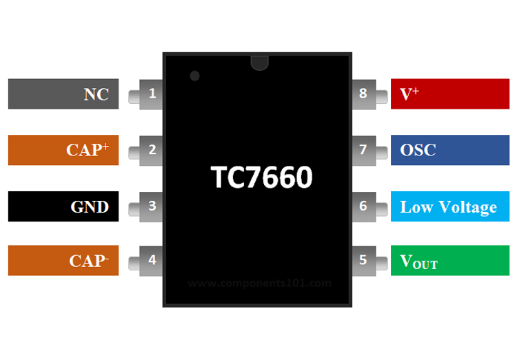
The TC7660 is an 8-pin IC. The pinout and descriptions are as follows:

Pin Number Pin Name Description
1 CAP+ Positive terminal for the external charge pump capacitor
2 GND Ground connection
3 CAP- Negative terminal for the external charge pump capacitor
4 VOUT Negative output voltage (-Vin)
5 LV Low-voltage pin (connect to GND for input voltages below 3.5V)
6 OSC Oscillator control pin (can be used to adjust the switching frequency)
7 V+ Positive input voltage
8 NC No connection (leave unconnected or use as a mechanical support if necessary)

Usage Instructions

How to Use the TC7660 in a Circuit

  1. Power Supply: Connect the positive voltage source to the V+ pin and ground to the GND pin.
  2. Charge Pump Capacitors:
    • Connect a capacitor (typically 10µF) between the CAP+ and CAP- pins. This capacitor is used for the charge pump operation.
    • Place another capacitor (typically 10µF) between the VOUT pin and GND to stabilize the output voltage.
  3. Low Voltage Operation: If the input voltage is below 3.5V, connect the LV pin to GND to optimize performance.
  4. Oscillator Control (Optional): The internal oscillator frequency can be adjusted by connecting an external capacitor or resistor to the OSC pin. For most applications, this pin can be left unconnected.

Example Circuit

Below is a basic circuit diagram for using the TC7660 to generate a -5V output from a +5V input:

   +5V ---- V+ (Pin 7)          CAP+ (Pin 1) ----||---- CAP- (Pin 3)
           |                                      |
          GND ---- GND (Pin 2)                    |
           |                                      |
          -5V ---- VOUT (Pin 4)                   |

Arduino UNO Example Code

The TC7660 can be used in conjunction with an Arduino UNO to power circuits requiring a negative voltage. Below is an example code snippet to demonstrate its use:

// Example: Using TC7660 to generate -5V for an op-amp circuit
// This code demonstrates how to monitor the input voltage using Arduino

const int inputVoltagePin = A0; // Analog pin to read input voltage
float inputVoltage = 0.0;

void setup() {
  Serial.begin(9600); // Initialize serial communication
  pinMode(inputVoltagePin, INPUT); // Set the pin as input
}

void loop() {
  // Read the input voltage (scaled to 0-5V range)
  int sensorValue = analogRead(inputVoltagePin);
  inputVoltage = sensorValue * (5.0 / 1023.0); // Convert ADC value to voltage

  // Print the input voltage to the Serial Monitor
  Serial.print("Input Voltage: ");
  Serial.print(inputVoltage);
  Serial.println(" V");

  delay(1000); // Wait for 1 second before the next reading
}

Important Considerations and Best Practices

  • Use low-ESR capacitors (e.g., ceramic or tantalum) for the charge pump and output capacitors to ensure stable operation.
  • Keep the capacitors as close as possible to the IC to minimize noise and improve performance.
  • Avoid exceeding the maximum input voltage (10V) or output current (20mA) to prevent damage to the IC.
  • If the output voltage is unstable, check the capacitor values and connections.

Troubleshooting and FAQs

Common Issues and Solutions

  1. Output Voltage is Incorrect or Unstable:

    • Ensure the charge pump and output capacitors are properly connected and have the correct values (typically 10µF).
    • Verify that the input voltage is within the specified range (1.5V to 10V).
    • Check for loose connections or poor solder joints.
  2. Excessive Heat Generation:

    • Ensure the output current does not exceed the maximum rating of 20mA.
    • Verify that the input voltage is not higher than 10V.
  3. No Output Voltage:

    • Confirm that the LV pin is connected to GND if the input voltage is below 3.5V.
    • Check the polarity of the capacitors and ensure they are not damaged.

FAQs

Q: Can the TC7660 provide a regulated output voltage?
A: No, the TC7660 is not a voltage regulator. The output voltage is approximately equal to the negative of the input voltage (-Vin), minus a small voltage drop due to internal resistance.

Q: What happens if I use capacitors with values other than 10µF?
A: The TC7660 can work with other capacitor values, but the performance may vary. Larger capacitors can improve stability, while smaller capacitors may result in higher ripple or instability.

Q: Can I use the TC7660 with an input voltage higher than 10V?
A: No, exceeding the maximum input voltage of 10V can damage the IC. Use a voltage regulator if a higher input voltage needs to be stepped down.

By following this documentation, you can effectively integrate the TC7660 into your circuits and troubleshoot common issues.