How to Use 5V Step-down V regulator: Examples, Pinouts, and Specs
Introduction
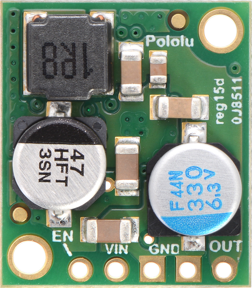
The Pololu 5V Step-down Voltage Regulator (Part ID: 2851) is a compact and efficient device designed to reduce a higher input voltage to a stable 5V output. This regulator is ideal for powering low-voltage devices from higher-voltage power sources, such as batteries or power adapters. Its high efficiency and small form factor make it a popular choice for portable electronics, robotics, and embedded systems.
Explore Projects Built with 5V Step-down V regulator


Explore Projects Built with 5V Step-down V regulator
Common Applications and Use Cases
- Powering microcontrollers (e.g., Arduino, Raspberry Pi) from higher-voltage sources.
- Supplying 5V to sensors, modules, and other low-voltage components.
- Battery-powered projects requiring efficient voltage regulation.
- Robotics and automation systems with mixed-voltage requirements.
Technical Specifications
Key Technical Details
- Input Voltage Range: 5.1V to 36V
- Output Voltage: 5V (regulated)
- Maximum Output Current: 500 mA
- Efficiency: Up to 90% (depending on input voltage and load)
- Quiescent Current: Approximately 200 µA
- Operating Temperature Range: -40°C to +85°C
- Dimensions: 12.7 mm × 10.2 mm × 3.8 mm
- Weight: 0.5 g
Pin Configuration and Descriptions
The Pololu 2851 regulator has three pins for easy integration into circuits. Below is the pinout:
| Pin | Name | Description |
|---|---|---|
| 1 | VIN | Input voltage pin. Connect to the higher voltage source (5.1V to 36V). |
| 2 | GND | Ground pin. Connect to the ground of the circuit. |
| 3 | VOUT | Regulated 5V output pin. Connect to the load or device requiring 5V power. |
Usage Instructions
How to Use the Component in a Circuit
Connect the Input Voltage (VIN):
Attach the VIN pin to a power source with a voltage between 5.1V and 36V. Ensure the input voltage is within this range to avoid damaging the regulator.Connect the Ground (GND):
Connect the GND pin to the ground of your circuit. This establishes a common reference point for the input and output.Connect the Output Voltage (VOUT):
Attach the VOUT pin to the device or circuit requiring a 5V power supply. Ensure the load does not exceed the maximum output current of 500 mA.Add Capacitors (Optional):
For improved stability, you can add a capacitor (e.g., 10 µF) across the VIN and GND pins and another across the VOUT and GND pins. This is especially useful in circuits with high-frequency noise.
Important Considerations and Best Practices
- Input Voltage Range: Always ensure the input voltage is above 5.1V and below 36V. Exceeding these limits can damage the regulator.
- Heat Dissipation: While the regulator is efficient, it may generate heat under high loads. Ensure adequate ventilation or heat sinking if necessary.
- Polarity Protection: The regulator does not have built-in reverse polarity protection. Double-check connections to avoid damage.
- Load Current: Do not exceed the maximum output current of 500 mA to prevent overheating or failure.
Example: Using with an Arduino UNO
The Pololu 2851 regulator can be used to power an Arduino UNO from a 12V battery. Below is an example circuit and Arduino code:
Circuit Connections
- Connect the 12V battery's positive terminal to the VIN pin of the regulator.
- Connect the battery's negative terminal to the GND pin of the regulator.
- Connect the VOUT pin of the regulator to the Arduino UNO's 5V pin.
- Connect the regulator's GND pin to the Arduino UNO's GND pin.
Arduino Code Example
// Example code to blink an LED connected to pin 13 of the Arduino UNO
// Ensure the Arduino is powered via the 5V Step-down Voltage Regulator

void setup() {
  pinMode(13, OUTPUT); // Set pin 13 as an output
}

void loop() {
  digitalWrite(13, HIGH); // Turn the LED on
  delay(1000);            // Wait for 1 second
  digitalWrite(13, LOW);  // Turn the LED off
  delay(1000);            // Wait for 1 second
}
Troubleshooting and FAQs
Common Issues and Solutions
| Issue | Possible Cause | Solution |
|---|---|---|
| No output voltage | Input voltage is below 5.1V or connections are incorrect | Verify input voltage and ensure proper connections to VIN, GND, and VOUT. |
| Regulator overheating | Load current exceeds 500 mA | Reduce the load or use a higher-capacity regulator. |
| Output voltage fluctuates | Insufficient input/output capacitors | Add capacitors (e.g., 10 µF) across VIN-GND and VOUT-GND. |
| Device connected to VOUT is not working | Voltage drop due to high input ripple or long wires | Use shorter wires and add decoupling capacitors near the load. |
FAQs
Can I use this regulator with a 3.7V LiPo battery?
No, the input voltage must be at least 5.1V. A 3.7V LiPo battery is insufficient.What happens if I reverse the input polarity?
The regulator does not have reverse polarity protection and may be permanently damaged. Always double-check connections.Can I use this regulator to power a Raspberry Pi?
While the regulator provides 5V, the maximum output current is 500 mA, which may not be sufficient for a Raspberry Pi under load. Consider a higher-capacity regulator for such applications.Is it safe to use this regulator in outdoor projects?
The regulator operates in a wide temperature range (-40°C to +85°C), but ensure it is protected from moisture and extreme environmental conditions.
This concludes the documentation for the Pololu 5V Step-down Voltage Regulator (Part ID: 2851). For further details, refer to the manufacturer's datasheet or contact Pololu support.