How to Use Bi-Directional Logic Level Converter: Examples, Pinouts, and Specs
Introduction
The Bi-Directional Logic Level Converter is an essential module for interfacing between digital circuits that operate at different voltage levels. It is particularly useful when connecting a 3.3V device to a 5V system, which is a common scenario in microcontroller applications such as interfacing an Arduino UNO (operating at 5V) with modern sensors or modules that operate at 3.3V. This converter features four independent channels, allowing for the simultaneous conversion of up to four signals.
Explore Projects Built with Bi-Directional Logic Level Converter


Explore Projects Built with Bi-Directional Logic Level Converter
Common Applications and Use Cases
- Interfacing 5V microcontrollers with 3.3V sensors
- Connecting 3.3V peripherals to a 5V system
- Bridging communication between microcontrollers with different operating voltages
- Prototyping with mixed-voltage systems
Technical Specifications
Key Technical Details
- Bidirectional voltage conversion between:
- High Voltage (HV) side: typically 5V
- Low Voltage (LV) side: typically 3.3V
- Maximum current per channel: 50 mA
- Quiescent current: <1 mA
- Logic level conversion for both digital and analog signals
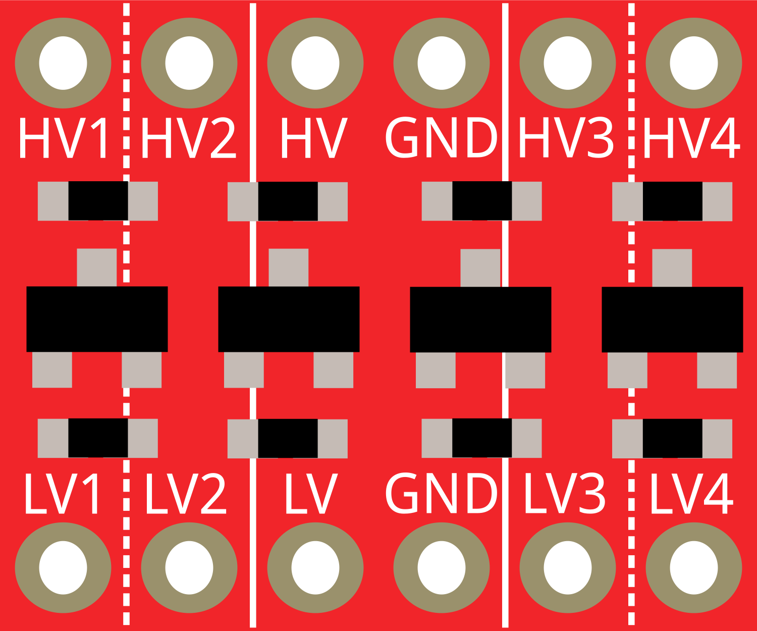
Pin Configuration and Descriptions
| Pin Name | Description |
|---|---|
| HV | High Voltage Supply Input (e.g., 5V) |
| GND | Ground (common ground between HV and LV) |
| LV | Low Voltage Supply Input (e.g., 3.3V) |
| GND | Ground (common ground between HV and LV) |
| HV1-HV4 | High Voltage Logic Input/Output Channels |
| LV1-LV4 | Low Voltage Logic Input/Output Channels |
Usage Instructions
How to Use the Component in a Circuit
- Connect the HV pin to the higher voltage level (e.g., 5V).
- Connect one GND pin to the ground of the higher voltage level system.
- Connect the LV pin to the lower voltage level (e.g., 3.3V).
- Connect the other GND pin to the ground of the lower voltage level system.
- Connect the signal lines from the higher voltage system to HV1-HV4.
- Connect the signal lines from the lower voltage system to LV1-LV4.
Important Considerations and Best Practices
- Ensure that both the HV and LV power supplies are connected before applying any signals.
- Do not exceed the maximum current rating of 50 mA per channel.
- Avoid applying signals that are outside the voltage range of the connected devices.
- Use pull-up resistors if required by the logic level specifications of the devices being interfaced.
Troubleshooting and FAQs
Common Issues Users Might Face
- Signal not converting properly: Check that the power supplies are connected correctly and that the common ground is established between the HV and LV sides.
- Device not recognizing signals: Ensure that the signal voltage levels are within the acceptable range for the device. Use pull-up resistors if necessary.
Solutions and Tips for Troubleshooting
- Double-check wiring and solder connections for any loose or incorrect connections.
- Measure the voltage levels on the HV and LV sides with a multimeter to ensure proper levels.
- If using with an Arduino UNO, ensure that the board is powered and functioning correctly.
FAQs
Q: Can the logic level converter be used with analog signals? A: Yes, the converter can be used with both digital and analog signals within the specified voltage ranges.
Q: Is it necessary to use all four channels? A: No, you can use as many channels as needed for your application.
Q: Can this converter be used for I2C or SPI communication? A: Yes, the converter can be used for I2C or SPI communication, but make sure to check the specific requirements for pull-up resistors and signal integrity.
Example Arduino UNO Code
Below is an example of how to use the Bi-Directional Logic Level Converter with an Arduino UNO to interface with a 3.3V I2C sensor.
#include <Wire.h>

void setup() {
  Wire.begin(); // Initialize I2C
  Serial.begin(9600); // Start serial communication at 9600 baud

  // Setup for Logic Level Converter
  pinMode(A4, INPUT_PULLUP); // SDA with pull-up resistor
  pinMode(A5, INPUT_PULLUP); // SCL with pull-up resistor

  // Additional sensor setup code here
}

void loop() {
  // Code to communicate with the sensor
  // Remember to connect SDA and SCL to the appropriate LV1 and LV2 channels
  // on the Logic Level Converter, and the HV1 and HV2 channels to the Arduino

  // Example I2C read from a sensor with address 0x3C
  Wire.beginTransmission(0x3C);
  Wire.write(byte(0x00)); // Write register address
  Wire.endTransmission();
  Wire.requestFrom(0x3C, 1); // Request 1 byte from the sensor

  if (Wire.available()) {
    byte data = Wire.read(); // Read the byte
    Serial.println(data); // Print the data to the serial monitor
  }

  delay(1000); // Wait for 1 second before the next read
}
Remember to adjust the code to match the specific requirements of the sensor or device you are interfacing with. The comments in the code are wrapped to ensure they do not exceed 80 characters per line, adhering to best practices for code readability and maintenance.