Cirkit Designer Logo
Cirkit Designer
Your all-in-one circuit design IDE
Home / 
Component Documentation

How to Use RS485 to USB: Examples, Pinouts, and Specs

Image of RS485 to USB
Cirkit Designer LogoDesign with RS485 to USB in Cirkit Designer

Introduction

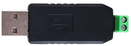
The RS485 to USB converter is an essential device that bridges the communication gap between RS485 protocol-based devices and computers or other USB-enabled devices. RS485 is a standard defining the electrical characteristics of drivers and receivers for use in serial communications systems. It is widely used in industrial and commercial applications due to its ability to support multiple devices over long distances. The converter allows for the easy integration of RS485 devices into modern systems that primarily use USB interfaces.

Explore Projects Built with RS485 to USB

Use Cirkit Designer to design, explore, and prototype these projects online. Some projects support real-time simulation. Click "Open Project" to start designing instantly!
Arduino Nano-Based RS485 Communication Interface with LED Indicators
Image of RS485: A project utilizing RS485 to USB in a practical application
This circuit is designed for serial communication between two Arduino Nano microcontrollers and a computer, using RS485 transceivers for differential signaling. Each Arduino also interfaces with a trimmer potentiometer for analog input and controls an LED, indicating status or providing user feedback.
Cirkit Designer LogoOpen Project in Cirkit Designer
Arduino UNO and Relay-Controlled RS485 Communication System
Image of Diagrama: A project utilizing RS485 to USB in a practical application
This circuit features an Arduino UNO microcontroller interfaced with a 4-channel relay module and a UART TTL to RS485 converter. The Arduino controls the relays via digital pins and communicates with the RS485 converter for serial communication, enabling control of external devices and communication over long distances.
Cirkit Designer LogoOpen Project in Cirkit Designer
Arduino Nano-Based Smart Relay Controller with RS485 Communication
Image of RELAY RS485: A project utilizing RS485 to USB in a practical application
This circuit features an Arduino Nano controlling an 8-channel relay module, with each relay channel connected to digital pins D2 through D9. Additionally, the Arduino interfaces with an RS485 module for serial communication, which is connected to an RS485 to USB converter. Power is supplied through an LM2596 step-down module.
Cirkit Designer LogoOpen Project in Cirkit Designer
STM32 and Arduino UNO Based Dual RS485 Communication Interface
Image of STM to Arduino RS485: A project utilizing RS485 to USB in a practical application
This circuit consists of two microcontrollers, an STM32F103C8T6 and an Arduino UNO, each interfaced with separate RS485 transceiver modules for serial communication. The STM32F103C8T6 controls the RE (Receiver Enable) and DE (Driver Enable) pins of one RS485 module to manage its operation, and communicates via the A9 and A10 pins for DI (Data Input) and RO (Receiver Output), respectively. The Arduino UNO is similarly connected to another RS485 module, with digital pins D2 and D3 interfacing with DI and RO, and D8 controlling both RE and DE. The RS485 modules are connected to each other through their A and B differential communication lines, enabling serial data exchange between the two microcontrollers over a robust and long-distance capable RS485 network.
Cirkit Designer LogoOpen Project in Cirkit Designer

Explore Projects Built with RS485 to USB

Use Cirkit Designer to design, explore, and prototype these projects online. Some projects support real-time simulation. Click "Open Project" to start designing instantly!
Image of RS485: A project utilizing RS485 to USB in a practical application
Arduino Nano-Based RS485 Communication Interface with LED Indicators
This circuit is designed for serial communication between two Arduino Nano microcontrollers and a computer, using RS485 transceivers for differential signaling. Each Arduino also interfaces with a trimmer potentiometer for analog input and controls an LED, indicating status or providing user feedback.
Cirkit Designer LogoOpen Project in Cirkit Designer
Image of Diagrama: A project utilizing RS485 to USB in a practical application
Arduino UNO and Relay-Controlled RS485 Communication System
This circuit features an Arduino UNO microcontroller interfaced with a 4-channel relay module and a UART TTL to RS485 converter. The Arduino controls the relays via digital pins and communicates with the RS485 converter for serial communication, enabling control of external devices and communication over long distances.
Cirkit Designer LogoOpen Project in Cirkit Designer
Image of RELAY RS485: A project utilizing RS485 to USB in a practical application
Arduino Nano-Based Smart Relay Controller with RS485 Communication
This circuit features an Arduino Nano controlling an 8-channel relay module, with each relay channel connected to digital pins D2 through D9. Additionally, the Arduino interfaces with an RS485 module for serial communication, which is connected to an RS485 to USB converter. Power is supplied through an LM2596 step-down module.
Cirkit Designer LogoOpen Project in Cirkit Designer
Image of STM to Arduino RS485: A project utilizing RS485 to USB in a practical application
STM32 and Arduino UNO Based Dual RS485 Communication Interface
This circuit consists of two microcontrollers, an STM32F103C8T6 and an Arduino UNO, each interfaced with separate RS485 transceiver modules for serial communication. The STM32F103C8T6 controls the RE (Receiver Enable) and DE (Driver Enable) pins of one RS485 module to manage its operation, and communicates via the A9 and A10 pins for DI (Data Input) and RO (Receiver Output), respectively. The Arduino UNO is similarly connected to another RS485 module, with digital pins D2 and D3 interfacing with DI and RO, and D8 controlling both RE and DE. The RS485 modules are connected to each other through their A and B differential communication lines, enabling serial data exchange between the two microcontrollers over a robust and long-distance capable RS485 network.
Cirkit Designer LogoOpen Project in Cirkit Designer

Common Applications and Use Cases

  • Industrial automation systems
  • Building automation
  • Networked communication in security systems
  • Data acquisition and monitoring systems

Technical Specifications

Key Technical Details

  • Voltage Supply: 5V DC (from USB port)
  • RS485 Interface: Half-duplex with differential signaling
  • USB Interface: USB 2.0 (compatible with USB 1.1)
  • Baud Rate: Up to 3 Mbps (depending on the RS485 device capabilities)
  • Transmission Distance: Up to 1.2 km (4000 ft) at lower baud rates
  • Operating Temperature: -40°C to 85°C

Pin Configuration and Descriptions

Pin Number Signal Name Description
1 D+ USB Data+
2 D- USB Data-
3 GND Ground
4 VCC 5V Supply from USB
5 A RS485 non-inverting signal (also known as "+" or "D+")
6 B RS485 inverting signal (also known as "-" or "D-")
7 GND Signal Ground for RS485

Usage Instructions

How to Use the Component in a Circuit

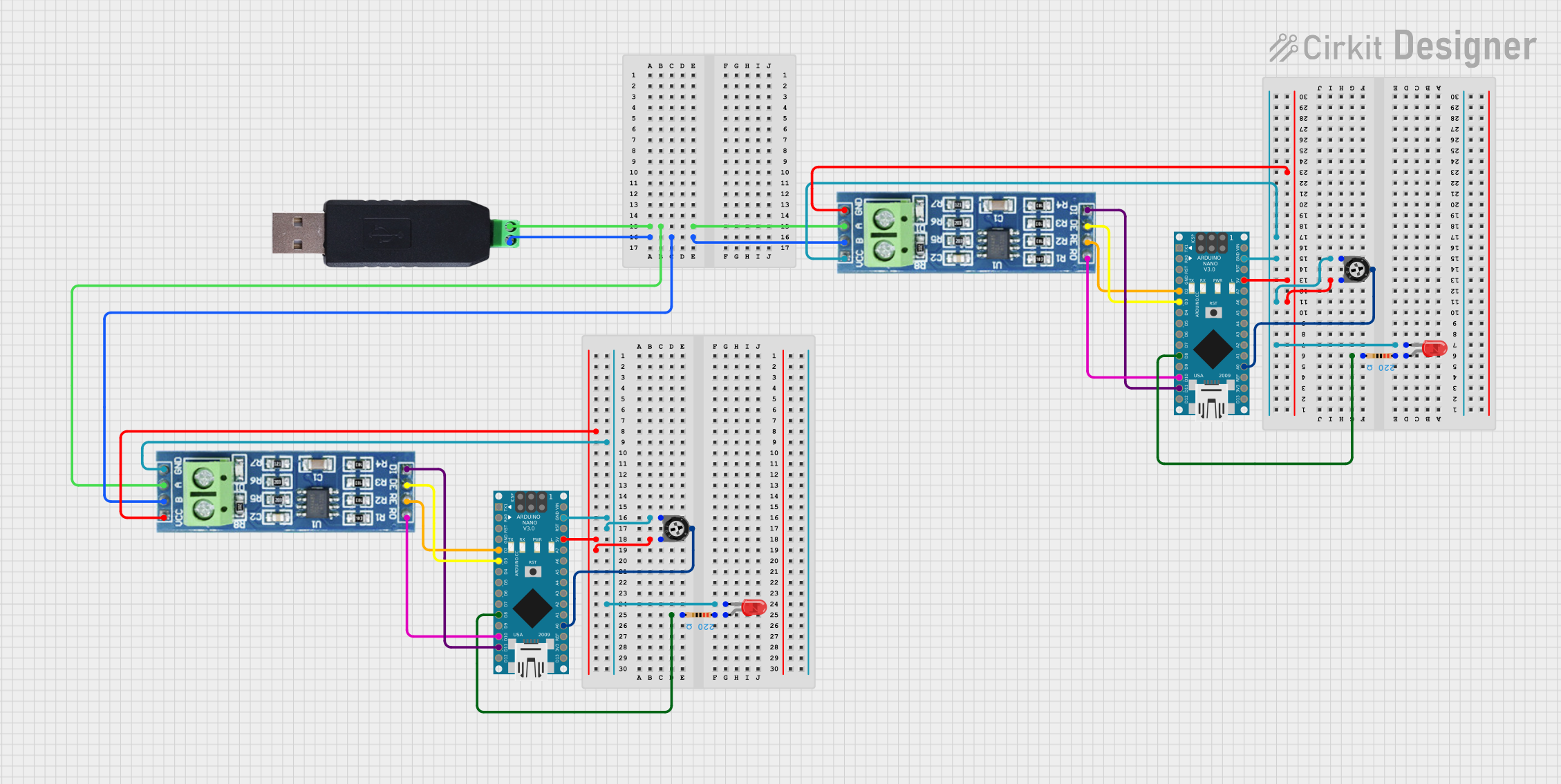
  1. Connect the USB connector of the RS485 to USB converter to the USB port of the computer or USB hub.
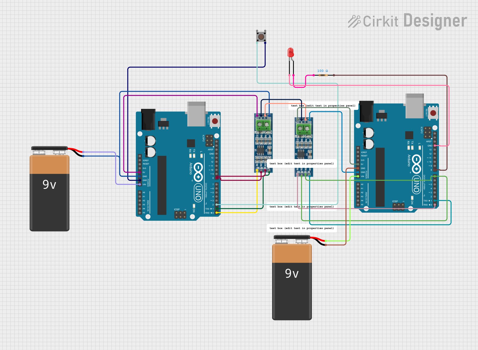
  2. Connect the RS485 terminals (A and B) to the corresponding terminals of the RS485 device you wish to communicate with.
  3. Ensure that the ground terminals (GND) of both the RS485 device and the converter are connected to a common ground reference.
  4. Install any necessary drivers for the converter on the computer, if not automatically recognized.

Important Considerations and Best Practices

  • Use twisted pair cables for the RS485 lines (A and B) to minimize electromagnetic interference.
  • Terminate the RS485 network with the appropriate termination resistors to prevent signal reflections.
  • Avoid running RS485 cables parallel to high-voltage or power cables.
  • Ensure that the cable length and baud rate are compatible to maintain signal integrity.

Troubleshooting and FAQs

Common Issues Users Might Face

  • Driver Installation: Ensure that the correct drivers are installed for the converter to function properly.
  • Signal Integrity: Check for proper termination and cable quality if communication errors occur.
  • Power Supply: Verify that the USB port is supplying adequate power to the converter.

Solutions and Tips for Troubleshooting

  • If the device is not recognized, try using a different USB port or reinstalling the drivers.
  • For communication issues, verify the wiring and termination resistors at both ends of the RS485 network.
  • Use a USB hub with an external power supply if the USB port cannot provide sufficient power.

FAQs

  • Q: Can I connect multiple RS485 devices to a single converter? A: Yes, RS485 supports multiple devices on the same bus, but ensure proper bus topology and termination.

  • Q: Is the converter compatible with all operating systems? A: Compatibility depends on the availability of drivers. Most converters support major operating systems like Windows, macOS, and Linux.

  • Q: How do I know if the converter is working? A: Most converters have LED indicators for power and data transmission. If these are active, the converter is likely functioning.

Example Code for Arduino UNO

#include <SoftwareSerial.h>

// Create a software serial port called "RS485Serial"
SoftwareSerial RS485Serial(10, 11); // RX, TX

void setup() {
  // Start the built-in serial port, for debugging
  Serial.begin(9600);
  // Start the RS485 connection
  RS485Serial.begin(4800);
}

void loop() {
  if (RS485Serial.available()) { // If data is available to read,
    char data = RS485Serial.read(); // read it
    Serial.print(data); // and print it to the serial monitor.
  }
  
  if (Serial.available()) { // If data is entered in the serial monitor,
    char data = Serial.read(); // read it
    RS485Serial.write(data); // and send it out RS485.
  }
}

Note: The above code is a simple example to demonstrate data transfer between the Arduino UNO and an RS485 device using a converter. Adjust the baud rate and pins according to your specific setup.