
How to Use LMD1820X: Examples, Pinouts, and Specs
 Design with LMD1820X in Cirkit Designer
Introduction
The LMD1820X is a high-performance dual H-bridge motor driver IC designed for driving DC motors and stepper motors. It is widely used in robotics, industrial automation, and other motor control applications due to its robust design and advanced features. The IC supports a supply voltage of up to 55V and can deliver a continuous output current of 3A per channel, making it suitable for medium to high-power motor control. Additionally, it includes built-in thermal shutdown and current limiting for enhanced reliability and protection.
Explore Projects Built with LMD1820X
 Open Project in Cirkit Designer
 Open Project in Cirkit Designer
 Open Project in Cirkit Designer
 Open Project in Cirkit Designer
Explore Projects Built with LMD1820X
Open Project in Cirkit DesignerOpen Project in Cirkit DesignerOpen Project in Cirkit DesignerOpen Project in Cirkit DesignerCommon Applications
- Robotics (e.g., motorized wheels, robotic arms)
- Industrial automation systems
- CNC machines and 3D printers
- Electric vehicles and drones
- Home appliances with motorized components
Technical Specifications
Key Specifications
| Parameter | Value |
|---|---|
| Supply Voltage (Vcc) | 8V to 55V |
| Continuous Output Current | 3A per channel |
| Peak Output Current | 6A per channel (short duration) |
| Logic Input Voltage | 0V to 5V (TTL/CMOS compatible) |
| Thermal Shutdown | Yes |
| Current Limiting | Yes |
| Operating Temperature | -40°C to +125°C |
| Package Type | TO-220 or similar |
Pin Configuration and Descriptions
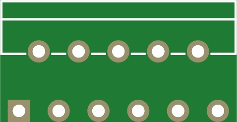
The LMD1820X typically comes in a 15-pin package. Below is the pinout and description:
| Pin Number | Pin Name | Description |
|---|---|---|
| 1 | OUT1A | Output for H-bridge 1 (Channel A) |
| 2 | OUT1B | Output for H-bridge 1 (Channel B) |
| 3 | GND | Ground connection |
| 4 | Vcc | Supply voltage for motor power (8V to 55V) |
| 5 | IN1A | Input signal for H-bridge 1 (Channel A) |
| 6 | IN1B | Input signal for H-bridge 1 (Channel B) |
| 7 | EN1 | Enable pin for H-bridge 1 (active high) |
| 8 | EN2 | Enable pin for H-bridge 2 (active high) |
| 9 | IN2A | Input signal for H-bridge 2 (Channel A) |
| 10 | IN2B | Input signal for H-bridge 2 (Channel B) |
| 11 | OUT2A | Output for H-bridge 2 (Channel A) |
| 12 | OUT2B | Output for H-bridge 2 (Channel B) |
| 13 | Vref | Reference voltage for current limiting |
| 14 | Thermal Flag | Thermal shutdown status output (active high when thermal shutdown occurs) |
| 15 | NC | No connection |
Usage Instructions
Using the LMD1820X in a Circuit
- Power Supply: Connect the motor power supply (8V to 55V) to the
Vccpin and ground to theGNDpin. Ensure the power supply can handle the current requirements of your motor. - Logic Inputs: Use the
IN1A,IN1B,IN2A, andIN2Bpins to control the direction of the motors. These pins are TTL/CMOS compatible and can be driven by a microcontroller like an Arduino. - Enable Pins: The
EN1andEN2pins must be set high to enable the respective H-bridges. If these pins are low, the outputs will be disabled. - Outputs: Connect the motor terminals to the
OUT1A,OUT1B,OUT2A, andOUT2Bpins as required. - Current Limiting: Use the
Vrefpin to set the current limit. Connect a resistor or voltage divider to adjust the reference voltage. - Thermal Protection: Monitor the
Thermal Flagpin to detect thermal shutdown conditions. If this pin goes high, reduce the load or improve cooling.
Example: Controlling a DC Motor with Arduino UNO
Below is an example of how to control a single DC motor using the LMD1820X and an Arduino UNO:
// Define motor control pins
const int EN1 = 9;  // Enable pin for H-bridge 1
const int IN1A = 7; // Input A for H-bridge 1
const int IN1B = 8; // Input B for H-bridge 1

void setup() {
  // Set pin modes
  pinMode(EN1, OUTPUT);
  pinMode(IN1A, OUTPUT);
  pinMode(IN1B, OUTPUT);

  // Enable the motor driver
  digitalWrite(EN1, HIGH);
}

void loop() {
  // Rotate motor in one direction
  digitalWrite(IN1A, HIGH);
  digitalWrite(IN1B, LOW);
  delay(2000); // Run for 2 seconds

  // Stop the motor
  digitalWrite(IN1A, LOW);
  digitalWrite(IN1B, LOW);
  delay(1000); // Pause for 1 second

  // Rotate motor in the opposite direction
  digitalWrite(IN1A, LOW);
  digitalWrite(IN1B, HIGH);
  delay(2000); // Run for 2 seconds

  // Stop the motor
  digitalWrite(IN1A, LOW);
  digitalWrite(IN1B, LOW);
  delay(1000); // Pause for 1 second
}
Best Practices
- Use decoupling capacitors near the
Vccpin to reduce noise and voltage spikes. - Ensure proper heat dissipation by attaching a heatsink to the IC if operating at high currents.
- Avoid exceeding the maximum voltage and current ratings to prevent damage.
- Use appropriate fuses or circuit breakers for additional protection.
Troubleshooting and FAQs
Common Issues and Solutions
Motor Not Spinning:
- Ensure the
EN1orEN2pin is set high to enable the H-bridge. - Verify the logic input signals (
IN1A,IN1B, etc.) are correctly configured. - Check the power supply voltage and current capacity.
- Ensure the
Thermal Shutdown Triggered:
- Reduce the motor load or improve cooling with a larger heatsink or active cooling.
- Verify the current limit is set correctly using the
Vrefpin.
Motor Vibrates but Does Not Rotate:
- Check the input signals to ensure they are not conflicting (e.g., both
IN1AandIN1Bset high). - Verify the motor connections to the output pins.
- Check the input signals to ensure they are not conflicting (e.g., both
Excessive Noise or Voltage Spikes:
- Add decoupling capacitors (e.g., 100µF electrolytic and 0.1µF ceramic) near the
Vccpin. - Use shielded cables for motor connections to reduce EMI.
- Add decoupling capacitors (e.g., 100µF electrolytic and 0.1µF ceramic) near the
FAQs
Q: Can the LMD1820X drive stepper motors?
A: Yes, the dual H-bridge configuration allows it to drive bipolar stepper motors. Use appropriate stepper motor control logic.
Q: What happens if the IC overheats?
A: The built-in thermal shutdown feature will disable the outputs to protect the IC. Reduce the load or improve cooling to resume operation.
Q: Can I use the LMD1820X with a 3.3V microcontroller?
A: Yes, the logic inputs are TTL/CMOS compatible and can accept signals as low as 3.3V.
Q: How do I set the current limit?
A: Connect a resistor or voltage divider to the Vref pin to adjust the reference voltage, which determines the current limit.