How to Use RGB Driver: Examples, Pinouts, and Specs
Introduction
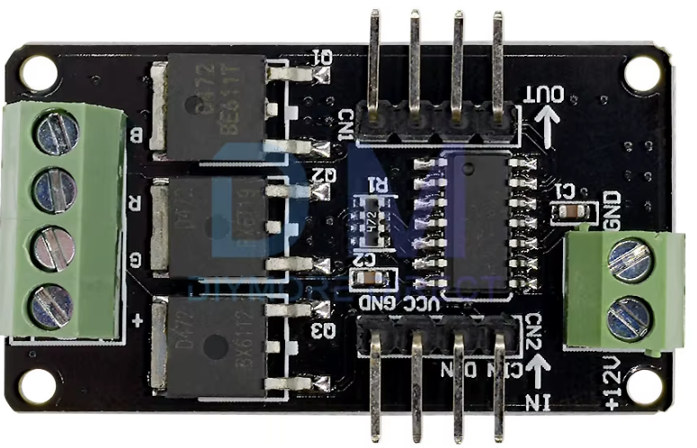
The RGB Driver, manufactured by Arduino, is an electronic component designed to control the color and brightness of RGB (Red, Green, Blue) LEDs. By adjusting the voltage and current supplied to each color channel, the RGB Driver enables precise control over the intensity of each color, allowing for the creation of millions of color combinations. This component is ideal for applications requiring dynamic lighting effects, such as decorative lighting, displays, and mood lighting.
Explore Projects Built with RGB Driver

Explore Projects Built with RGB Driver
Common Applications and Use Cases
- LED displays and signage
- Ambient lighting systems
- Smart home lighting
- Wearable electronics
- Robotics and hobby projects
Technical Specifications
The RGB Driver is designed to work seamlessly with RGB LEDs and microcontrollers like the Arduino UNO. Below are the key technical details:
General Specifications
| Parameter | Value |
|---|---|
| Operating Voltage | 5V to 12V |
| Output Channels | 3 (Red, Green, Blue) |
| Maximum Output Current | 500mA per channel |
| Control Method | PWM (Pulse Width Modulation) |
| Compatibility | Common cathode RGB LEDs |
| Operating Temperature | -20°C to 85°C |
Pin Configuration and Descriptions
| Pin Name | Pin Type | Description |
|---|---|---|
| VCC | Power Input | Connect to the positive voltage supply (5V-12V). |
| GND | Ground | Connect to the ground of the power supply. |
| R_PWM | PWM Input | PWM signal input for the Red channel. |
| G_PWM | PWM Input | PWM signal input for the Green channel. |
| B_PWM | PWM Input | PWM signal input for the Blue channel. |
| LED_R | Output | Connect to the Red pin of the RGB LED. |
| LED_G | Output | Connect to the Green pin of the RGB LED. |
| LED_B | Output | Connect to the Blue pin of the RGB LED. |
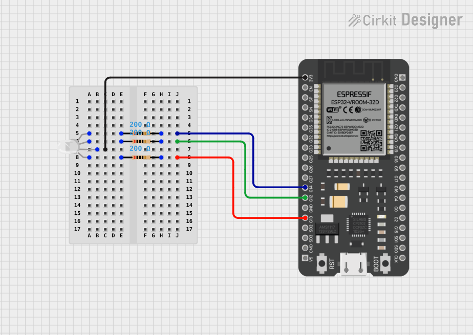
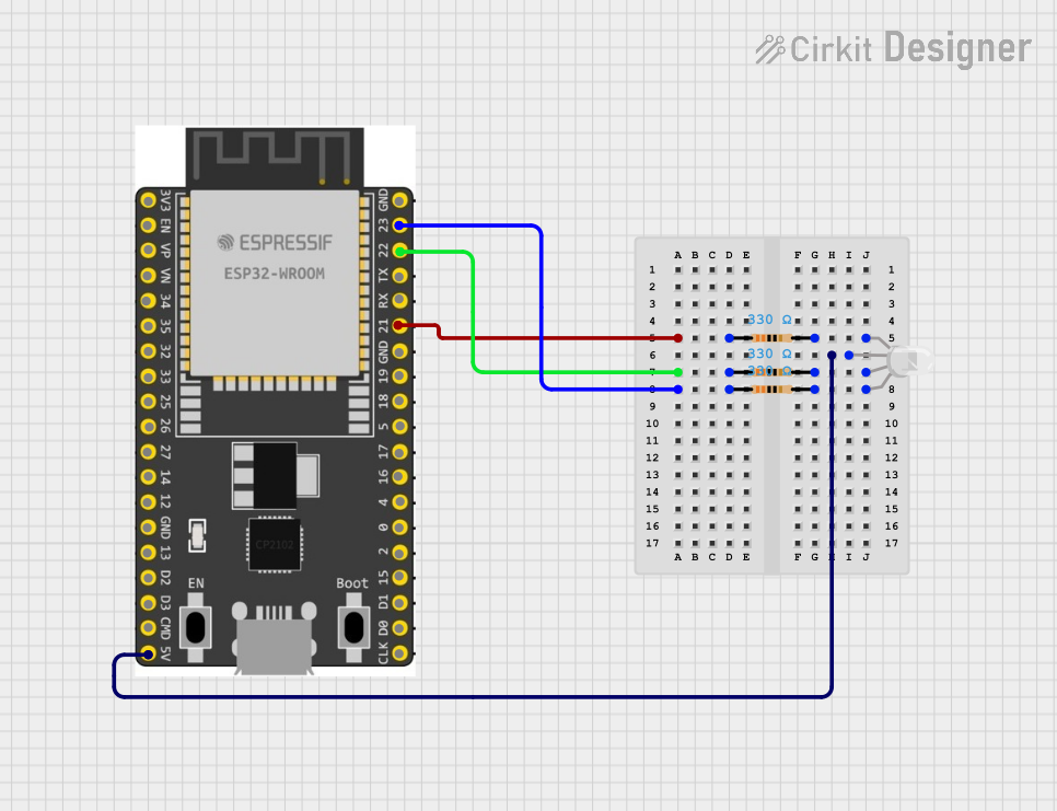
Usage Instructions
How to Use the RGB Driver in a Circuit
- Power Supply: Connect the VCC pin to a 5V-12V power source and the GND pin to the ground.
- Microcontroller Connection: Connect the R_PWM, G_PWM, and B_PWM pins to PWM-capable pins on your Arduino UNO or other microcontroller.
- LED Connection: Connect the LED_R, LED_G, and LED_B pins to the corresponding pins of a common cathode RGB LED.
- Programming: Use PWM signals to control the brightness of each color channel. By varying the duty cycle of the PWM signals, you can create different colors.
Important Considerations and Best Practices
- Ensure the total current drawn by the RGB LED does not exceed the maximum output current of 500mA per channel.
- Use appropriate resistors in series with the RGB LED to limit current and prevent damage to the LED.
- Avoid connecting the RGB Driver to a power supply voltage outside the specified range (5V-12V).
- For optimal performance, use a common cathode RGB LED, as the driver is designed for this configuration.
Example Code for Arduino UNO
Below is an example code snippet to control an RGB LED using the RGB Driver and an Arduino UNO:
// Define PWM pins for RGB channels
const int redPin = 9;   // Connect to R_PWM pin of the RGB Driver
const int greenPin = 10; // Connect to G_PWM pin of the RGB Driver
const int bluePin = 11;  // Connect to B_PWM pin of the RGB Driver

void setup() {
  // Set RGB pins as output
  pinMode(redPin, OUTPUT);
  pinMode(greenPin, OUTPUT);
  pinMode(bluePin, OUTPUT);
}

void loop() {
  // Example: Cycle through Red, Green, and Blue colors
  analogWrite(redPin, 255);   // Full brightness for Red
  analogWrite(greenPin, 0);   // Turn off Green
  analogWrite(bluePin, 0);    // Turn off Blue
  delay(1000);                // Wait for 1 second

  analogWrite(redPin, 0);     // Turn off Red
  analogWrite(greenPin, 255); // Full brightness for Green
  analogWrite(bluePin, 0);    // Turn off Blue
  delay(1000);                // Wait for 1 second

  analogWrite(redPin, 0);     // Turn off Red
  analogWrite(greenPin, 0);   // Turn off Green
  analogWrite(bluePin, 255);  // Full brightness for Blue
  delay(1000);                // Wait for 1 second
}
Troubleshooting and FAQs
Common Issues and Solutions
LED Not Lighting Up
- Cause: Incorrect wiring or loose connections.
- Solution: Double-check all connections, ensuring the RGB LED is connected to the correct pins on the RGB Driver.
Incorrect Colors Displayed
- Cause: PWM signals are not configured correctly.
- Solution: Verify the PWM pin assignments in your code and ensure the duty cycles are set appropriately.
LED Flickering
- Cause: Insufficient power supply or unstable PWM signals.
- Solution: Use a stable power source and ensure the microcontroller is outputting clean PWM signals.
Overheating
- Cause: Excessive current draw or insufficient cooling.
- Solution: Use current-limiting resistors and ensure the RGB Driver is not operating beyond its maximum current rating.
FAQs
Q: Can I use a common anode RGB LED with this driver?
A: No, the RGB Driver is designed specifically for common cathode RGB LEDs.
Q: What is the maximum number of RGB LEDs I can connect?
A: The number depends on the total current draw. Ensure the combined current does not exceed 500mA per channel.
Q: Can I control the RGB Driver with a non-Arduino microcontroller?
A: Yes, as long as the microcontroller can output PWM signals compatible with the RGB Driver.
Q: Do I need external resistors for the RGB LED?
A: Yes, it is recommended to use appropriate resistors to limit the current and protect the LED from damage.