How to Use Pulse Sensor: Examples, Pinouts, and Specs
Introduction
The Pulse Sensor is a compact and easy-to-use device designed to detect and measure the pulse rate by monitoring blood flow through the skin. It is widely used in health and fitness applications, such as heart rate monitoring, fitness tracking, and biofeedback systems. The sensor is ideal for wearable devices and can be easily integrated into microcontroller-based projects, including Arduino and other development platforms.
Explore Projects Built with Pulse Sensor
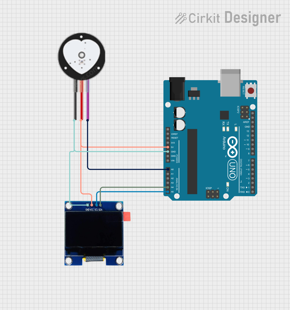
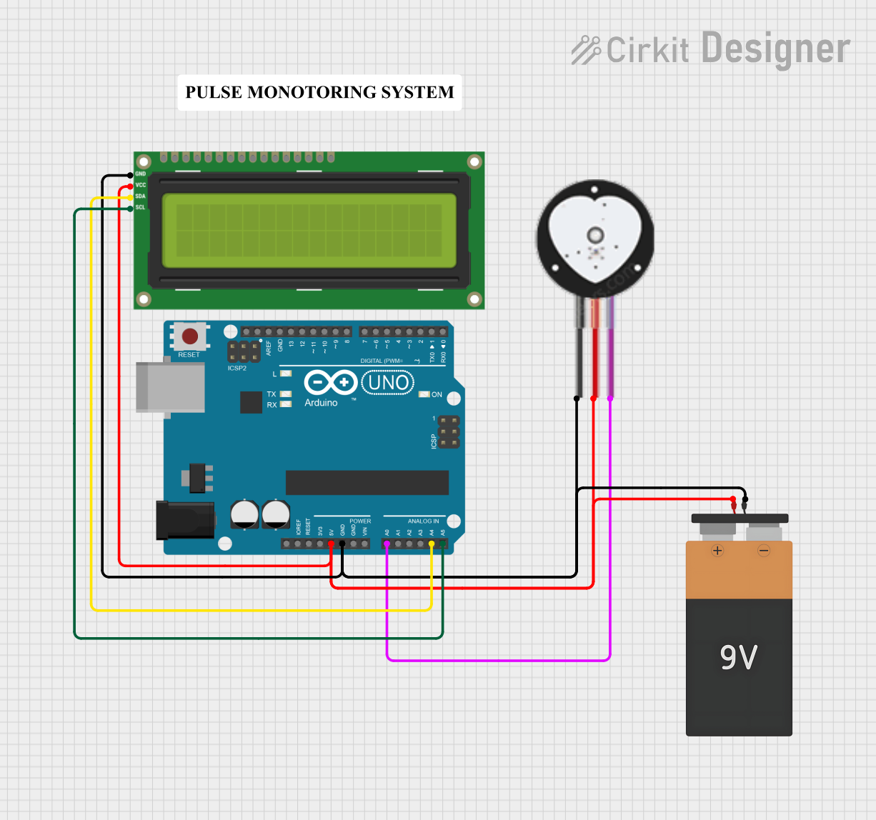
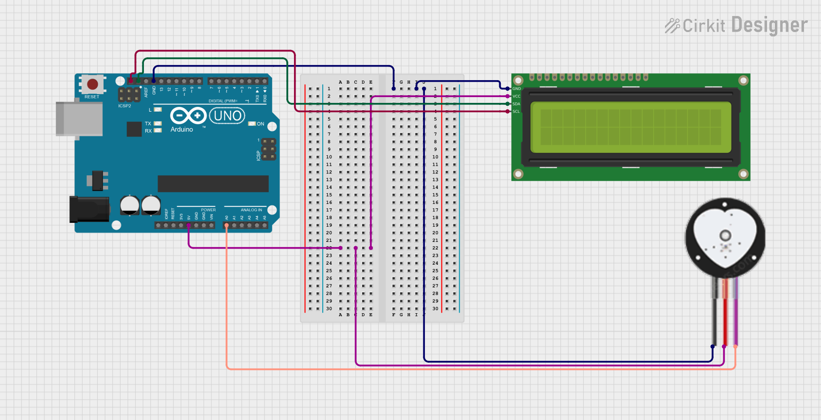
Explore Projects Built with Pulse Sensor
Technical Specifications
- Operating Voltage: 3.3V to 5V
- Current Consumption: ~4mA
- Output Signal: Analog
- Dimensions: 16mm diameter
- Weight: ~3 grams
- Cable Length: ~24 inches
- Sampling Rate: Up to 100 Hz
- Sensor Type: Photoplethysmography (PPG)
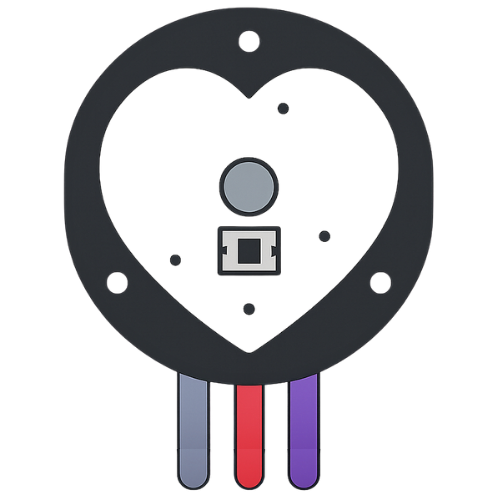
Pin Configuration and Descriptions
| Pin Name | Description |
|---|---|
| VCC | Power supply pin. Connect to 3.3V or 5V. |
| GND | Ground pin. Connect to the ground of the circuit. |
| SIG | Analog output pin. Provides the pulse signal as a varying voltage. |
Usage Instructions
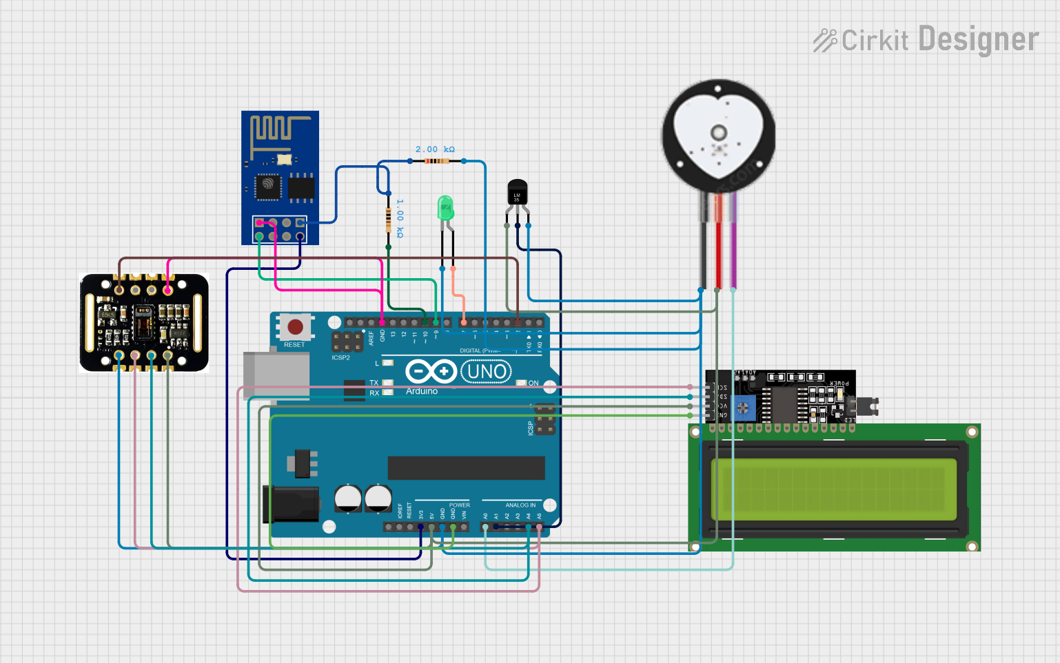
How to Use the Pulse Sensor in a Circuit
Connect the Pins:
- Connect the
VCCpin to the 3.3V or 5V power supply of your microcontroller. - Connect the
GNDpin to the ground of your circuit. - Connect the
SIGpin to an analog input pin on your microcontroller (e.g., A0 on Arduino UNO).
- Connect the
Place the Sensor:
- Attach the sensor to a fingertip or earlobe using the included Velcro strap or adhesive.
- Ensure the sensor is securely in place to avoid movement artifacts.
Read the Signal:
- Use the analog input of your microcontroller to read the signal from the
SIGpin. - Process the signal to extract the pulse rate.
- Use the analog input of your microcontroller to read the signal from the
Important Considerations and Best Practices
- Avoid excessive movement while using the sensor, as it may introduce noise into the signal.
- Ensure proper skin contact for accurate readings.
- Use a low-pass filter in your circuit or software to reduce noise and improve signal quality.
- If using with an Arduino, consider using the PulseSensor library for easier implementation.
Example Code for Arduino UNO
// Include the PulseSensor library
#include <PulseSensorPlayground.h>

// Define the analog pin connected to the Pulse Sensor
const int PULSE_PIN = A0;

// Create a PulseSensor object
PulseSensorPlayground pulseSensor;

// Variable to store the BPM (beats per minute)
int bpm;

void setup() {
  Serial.begin(9600); // Initialize serial communication for debugging

  // Configure the PulseSensor object
  pulseSensor.analogInput(PULSE_PIN);
  pulseSensor.setSerial(Serial); // Optional: Output data to Serial Monitor

  // Start the PulseSensor
  if (pulseSensor.begin()) {
    Serial.println("Pulse Sensor initialized successfully!");
  } else {
    Serial.println("Failed to initialize Pulse Sensor.");
  }
}

void loop() {
  // Read the pulse rate
  bpm = pulseSensor.getBeatsPerMinute();

  // Check if a valid BPM is detected
  if (pulseSensor.sawStartOfBeat()) {
    Serial.print("Heartbeat detected! BPM: ");
    Serial.println(bpm);
  }

  delay(20); // Small delay to allow for stable readings
}
Troubleshooting and FAQs
Common Issues and Solutions
No Signal Detected:
- Ensure the sensor is properly connected to the microcontroller.
- Verify that the
VCCandGNDpins are connected to the correct power supply and ground. - Check for proper skin contact and secure placement of the sensor.
Inconsistent Readings:
- Minimize movement during measurement to reduce noise.
- Use a low-pass filter in hardware or software to smooth the signal.
- Ensure the sensor is not exposed to excessive ambient light, which can interfere with readings.
High Noise in Signal:
- Check for loose connections in the circuit.
- Use shielded cables to reduce electromagnetic interference.
- Place the sensor in a stable and well-lit environment.
FAQs
Can the Pulse Sensor be used with a 3.3V microcontroller? Yes, the sensor operates at both 3.3V and 5V, making it compatible with a wide range of microcontrollers.
What is the maximum sampling rate of the Pulse Sensor? The sensor can sample up to 100 Hz, which is sufficient for most heart rate monitoring applications.
Can the Pulse Sensor be used for continuous monitoring? Yes, the sensor is designed for continuous use, but ensure proper placement and minimize movement for accurate readings.
Is the Pulse Sensor waterproof? No, the sensor is not waterproof. Avoid exposing it to water or excessive moisture.