
How to Use XT60 Connector: Examples, Pinouts, and Specs
 Design with XT60 Connector in Cirkit Designer
Introduction
The XT60 connector, manufactured by GENERIC, is a high-current electrical connector widely used in remote control (RC) applications, drones, electric vehicles, and other high-power systems. Its secure, polarized design ensures reliable connections while preventing reverse polarity. The XT60 connector is made from durable materials, including gold-plated contacts and heat-resistant nylon, making it suitable for high-current and high-temperature environments.
Explore Projects Built with XT60 Connector
 Open Project in Cirkit Designer
 Open Project in Cirkit Designer
 Open Project in Cirkit Designer
 Open Project in Cirkit Designer
Explore Projects Built with XT60 Connector
Open Project in Cirkit DesignerOpen Project in Cirkit DesignerOpen Project in Cirkit DesignerOpen Project in Cirkit DesignerCommon Applications
- RC vehicles (cars, boats, planes, and drones)
- Lithium Polymer (LiPo) battery connections
- Electric bikes and scooters
- Power distribution in DIY electronics projects
- High-current DC power systems
Technical Specifications
The XT60 connector is designed to handle high currents and provide a secure, low-resistance connection. Below are the key technical details:
| Parameter | Specification |
|---|---|
| Rated Current | 60A continuous |
| Peak Current | 100A (short duration) |
| Voltage Rating | Up to 500V DC |
| Contact Material | Gold-plated brass |
| Housing Material | Heat-resistant nylon (PA) |
| Operating Temperature | -20°C to 120°C |
| Connector Type | Male and Female (polarized) |
| Wire Compatibility | 12 AWG to 10 AWG |
Pin Configuration and Descriptions
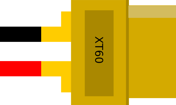
The XT60 connector consists of two pins: one for positive (+) and one for negative (-). The pins are polarized to prevent incorrect connections.
| Pin | Description | Notes |
|---|---|---|
| + | Positive terminal | Connects to the positive side of the circuit or battery. |
| - | Negative terminal | Connects to the negative side of the circuit or battery. |
Usage Instructions
How to Use the XT60 Connector in a Circuit
- Prepare the Wires: Strip the insulation from the ends of the wires you want to connect. Ensure the wire gauge is compatible (12 AWG to 10 AWG is recommended).
- Solder the Wires:
- Heat the soldering iron to the appropriate temperature (around 350°C to 400°C).
- Tin the exposed wire ends by applying a small amount of solder.
- Insert the tinned wire into the XT60 connector's solder cup and apply heat to secure the connection.
- Check Polarity: Ensure the positive wire is connected to the "+" terminal and the negative wire to the "-" terminal.
- Secure the Connection: Slide heat shrink tubing over the soldered joint and apply heat to insulate and protect the connection.
- Connect the XT60 Pair: Plug the male and female connectors together. The polarized design ensures proper alignment.
Important Considerations and Best Practices
- Avoid Overheating: Excessive heat during soldering can damage the nylon housing. Use a soldering iron with a fine tip and work quickly.
- Check for Shorts: After soldering, inspect the connections for any solder bridges or shorts between the terminals.
- Use Heat Shrink Tubing: Always insulate the soldered connections to prevent accidental short circuits.
- Match Connector Types: Ensure you are using a compatible XT60 male and female pair.
- Avoid Overcurrent: Do not exceed the rated current of 60A to prevent overheating or damage.
Example: Connecting an XT60 to an Arduino UNO
While the XT60 connector is not directly compatible with the Arduino UNO, it can be used to supply power to the Arduino through a DC barrel jack or VIN pin. Below is an example of how to use an XT60 connector with a LiPo battery to power an Arduino UNO:
- Connect the XT60 connector to the LiPo battery.
- Use a DC-DC step-down converter to reduce the voltage to 5V (for USB power) or 7-12V (for VIN pin).
- Connect the output of the step-down converter to the Arduino UNO.
// Example code to blink an LED on Arduino UNO
// Ensure the Arduino is powered via the XT60-connected battery

void setup() {
  pinMode(13, OUTPUT); // Set pin 13 as an output for the onboard LED
}

void loop() {
  digitalWrite(13, HIGH); // Turn the LED on
  delay(1000);            // Wait for 1 second
  digitalWrite(13, LOW);  // Turn the LED off
  delay(1000);            // Wait for 1 second
}
Troubleshooting and FAQs
Common Issues
Loose Connections:
- Cause: Improper soldering or insufficient wire insertion.
- Solution: Re-solder the connection, ensuring the wire is fully inserted into the solder cup.
Overheating During Soldering:
- Cause: Prolonged application of heat to the connector.
- Solution: Use a soldering iron with a fine tip and work quickly. Allow the connector to cool between soldering attempts.
Reverse Polarity Connection:
- Cause: Incorrect wiring of the positive and negative terminals.
- Solution: Double-check the polarity before soldering and connecting the XT60 pair.
Connector Does Not Fit:
- Cause: Using incompatible or damaged XT60 connectors.
- Solution: Ensure both connectors are genuine XT60 and inspect for physical damage.
FAQs
Q: Can the XT60 connector handle currents above 60A?
A: The XT60 connector can handle peak currents of up to 100A for short durations. However, for continuous operation, it is recommended to stay within the 60A rating to avoid overheating.
Q: Is the XT60 connector waterproof?
A: No, the XT60 connector is not waterproof. If used in wet environments, additional waterproofing measures, such as heat shrink tubing with adhesive, should be applied.
Q: Can I use the XT60 connector with smaller wire gauges?
A: Yes, but it is not recommended. Smaller wires may not provide sufficient current-carrying capacity and could lead to overheating or voltage drops.
Q: How do I disconnect the XT60 connectors?
A: Hold the connectors firmly by their housings and pull them apart. Avoid pulling on the wires to prevent damage.