How to Use LED Driver TLC59711: Examples, Pinouts, and Specs
Introduction
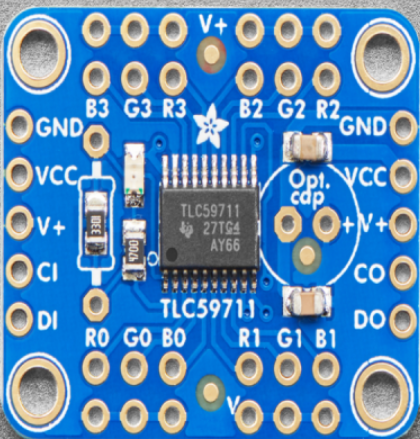
The TLC59711 is a 16-channel LED driver with an integrated PWM (Pulse Width Modulation) controller, designed to provide precise control over RGB LEDs. This component is ideal for applications requiring high-resolution dimming, color mixing, and low power consumption. With its programmable brightness and grayscale control, the TLC59711 is widely used in LED displays, architectural lighting, and decorative lighting systems.
Explore Projects Built with LED Driver TLC59711
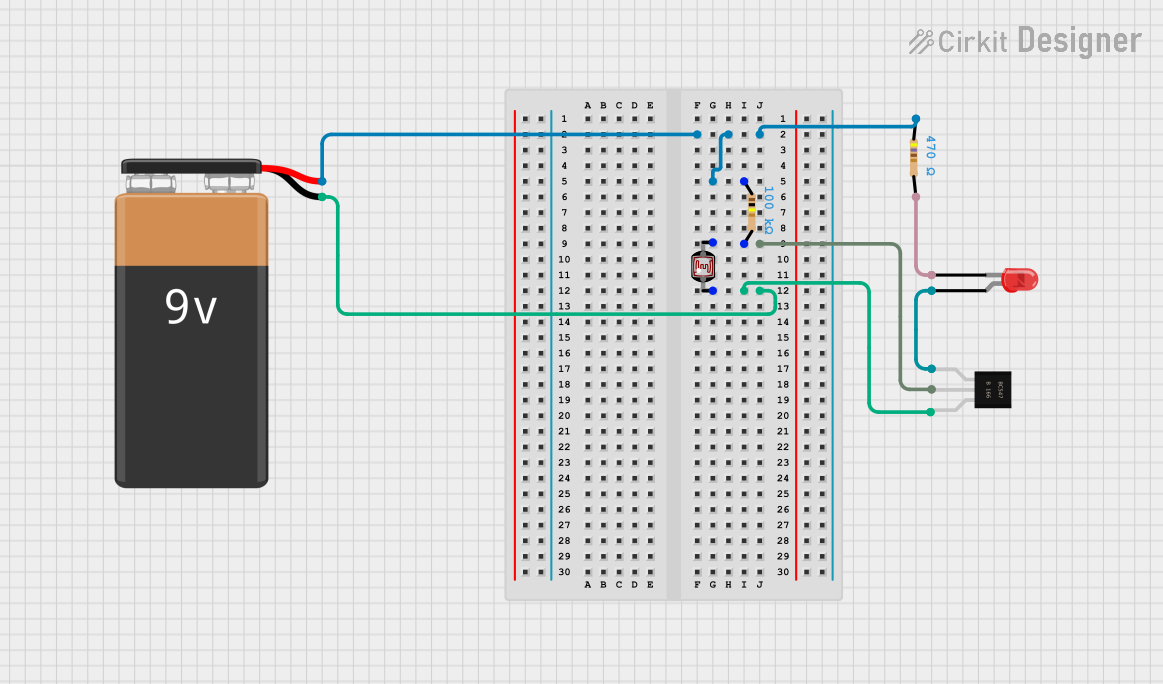
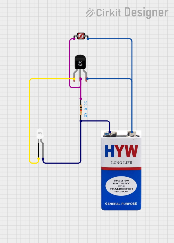
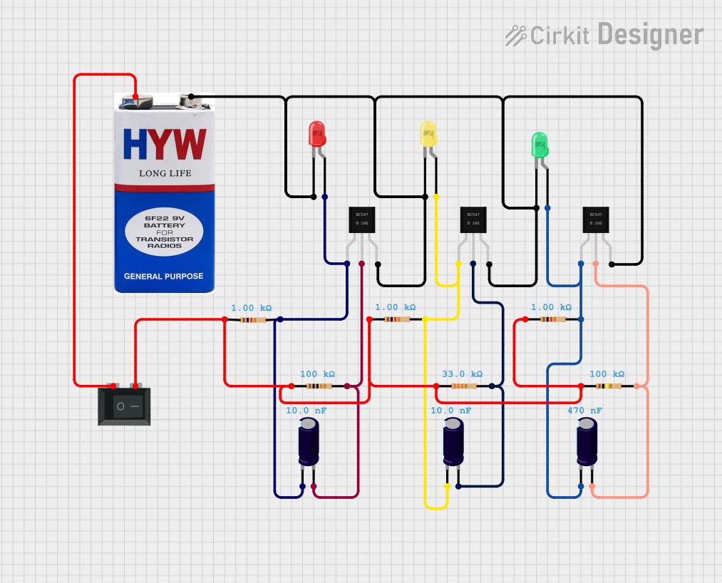

Explore Projects Built with LED Driver TLC59711
Common Applications:
- RGB LED displays and panels
- Architectural and decorative lighting
- Stage lighting and effects
- Industrial and commercial lighting systems
- Any application requiring precise LED control
Technical Specifications
The TLC59711 offers advanced features and robust performance for LED driving. Below are its key technical specifications:
| Parameter | Value |
|---|---|
| Supply Voltage (Vcc) | 3.0V to 5.5V |
| Output Channels | 16 |
| Maximum Output Current | 60mA per channel |
| PWM Resolution | 16-bit (65536 levels) |
| Grayscale Control | 16-bit per channel |
| Brightness Control | 7-bit global brightness control |
| Communication Interface | Serial (SPI-like protocol) |
| Operating Temperature Range | -40°C to +85°C |
| Package Type | HTSSOP-28 |
Pin Configuration and Descriptions
The TLC59711 comes in a 28-pin HTSSOP package. Below is the pin configuration and description:
| Pin Number | Pin Name | Description |
|---|---|---|
| 1 | OUT0 | Output channel 0 for driving LEDs |
| 2 | OUT1 | Output channel 1 for driving LEDs |
| 3 | OUT2 | Output channel 2 for driving LEDs |
| 4 | OUT3 | Output channel 3 for driving LEDs |
| 5 | OUT4 | Output channel 4 for driving LEDs |
| 6 | OUT5 | Output channel 5 for driving LEDs |
| 7 | OUT6 | Output channel 6 for driving LEDs |
| 8 | OUT7 | Output channel 7 for driving LEDs |
| 9 | OUT8 | Output channel 8 for driving LEDs |
| 10 | OUT9 | Output channel 9 for driving LEDs |
| 11 | OUT10 | Output channel 10 for driving LEDs |
| 12 | OUT11 | Output channel 11 for driving LEDs |
| 13 | OUT12 | Output channel 12 for driving LEDs |
| 14 | OUT13 | Output channel 13 for driving LEDs |
| 15 | OUT14 | Output channel 14 for driving LEDs |
| 16 | OUT15 | Output channel 15 for driving LEDs |
| 17 | GND | Ground connection |
| 18 | VCC | Power supply input (3.0V to 5.5V) |
| 19 | SOUT | Serial data output for daisy-chaining multiple TLC59711 devices |
| 20 | SIN | Serial data input for receiving control data |
| 21 | SCLK | Serial clock input for synchronizing data transfer |
| 22 | LAT | Latch signal input to update the output registers |
| 23 | IREF | Reference current pin for setting the maximum output current |
| 24 | TEST | Test pin (must be connected to GND in normal operation) |
| 25-28 | NC | No connection |
Usage Instructions
The TLC59711 is straightforward to use in LED driving applications. Below are the steps and considerations for integrating it into your circuit:
Basic Circuit Setup
- Power Supply: Connect the VCC pin to a 3.0V to 5.5V power source and the GND pin to ground.
- LED Connections: Connect the cathodes of the LEDs to the output pins (OUT0 to OUT15). The anodes of the LEDs should be connected to a suitable power source through current-limiting resistors if needed.
- Reference Current: Connect a resistor between the IREF pin and GND to set the maximum output current for the LEDs. The resistor value determines the current limit.
- Control Signals: Use a microcontroller or other control device to send data to the SIN, SCLK, and LAT pins. The SOUT pin can be used to daisy-chain multiple TLC59711 devices.
Important Considerations
- Current Limiting: Ensure the IREF resistor is chosen correctly to prevent overdriving the LEDs.
- Thermal Management: If driving high currents, ensure proper heat dissipation to avoid overheating.
- Daisy-Chaining: When using multiple TLC59711 devices, connect the SOUT pin of one device to the SIN pin of the next.
Example Code for Arduino UNO
The TLC59711 can be controlled using an Arduino UNO. Below is an example code snippet to drive RGB LEDs:
#include <Adafruit_TLC59711.h>

// Define the number of TLC59711 drivers in the chain
#define NUM_TLC59711 1

// Define the pins for data and clock
#define DATA_PIN 11  // Arduino pin connected to SIN
#define CLOCK_PIN 13 // Arduino pin connected to SCLK

// Create an instance of the Adafruit_TLC59711 library
Adafruit_TLC59711 tlc = Adafruit_TLC59711(NUM_TLC59711, CLOCK_PIN, DATA_PIN);

void setup() {
  // Initialize the TLC59711 driver
  tlc.begin();

  // Set global brightness (0-127)
  tlc.setBrightness(127);

  // Set initial LED colors (16-bit values for each channel)
  tlc.setPWM(0, 65535); // Full brightness for channel 0 (Red)
  tlc.setPWM(1, 0);     // Off for channel 1 (Green)
  tlc.setPWM(2, 32768); // Half brightness for channel 2 (Blue)

  // Update the outputs
  tlc.write();
}

void loop() {
  // Example: Gradually dim the red channel
  for (uint16_t i = 65535; i > 0; i -= 1000) {
    tlc.setPWM(0, i); // Decrease brightness of channel 0
    tlc.write();      // Update the outputs
    delay(10);        // Small delay for smooth dimming
  }
}
Notes:
- Install the
Adafruit_TLC59711library in the Arduino IDE before using the code. - Adjust the brightness and PWM values as needed for your application.
Troubleshooting and FAQs
Common Issues
LEDs Not Lighting Up:
- Verify the power supply connections to the TLC59711 and LEDs.
- Check the IREF resistor value to ensure proper current settings.
- Ensure the SIN, SCLK, and LAT signals are correctly connected and configured.
Flickering LEDs:
- Ensure the data transfer timing matches the TLC59711's requirements.
- Check for loose connections or poor soldering.
Overheating:
- Verify that the output current does not exceed the maximum rating.
- Use proper heat dissipation techniques, such as heatsinks or ventilation.
FAQs
Q: Can I daisy-chain multiple TLC59711 devices?
A: Yes, connect the SOUT pin of one device to the SIN pin of the next. Ensure the data length is adjusted accordingly in your code.
Q: How do I calculate the IREF resistor value?
A: Use the formula: Iout = 39.06 / Rref, where Iout is the desired output current per channel in mA, and Rref is the resistor value in kΩ.
Q: What is the maximum number of LEDs I can control?
A: Each TLC59711 can control up to 16 LEDs. For more LEDs, daisy-chain multiple devices.
By following this documentation, you can effectively integrate the TLC59711 into your LED projects and achieve precise control over brightness and color.