Cirkit Designer Logo
Cirkit Designer
Your all-in-one circuit design IDE
Home / 
Component Documentation

How to Use GPS NEO 6M: Examples, Pinouts, and Specs

Image of GPS NEO 6M
Cirkit Designer LogoDesign with GPS NEO 6M in Cirkit Designer

Introduction

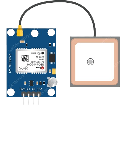
The GPS NEO 6M module is a compact, high-performance GPS (Global Positioning System) receiver with an integrated NEO 6M chipset that provides accurate positioning and navigation information. This module is widely used in various applications such as drones, vehicle tracking systems, personal navigation devices, and time synchronization.

Explore Projects Built with GPS NEO 6M

Use Cirkit Designer to design, explore, and prototype these projects online. Some projects support real-time simulation. Click "Open Project" to start designing instantly!
Arduino Mega 2560 GPS Data Logger with NEO 6M Module
Image of Dhanshri project: A project utilizing GPS NEO 6M in a practical application
This circuit interfaces a GPS NEO 6M module with an Arduino Mega 2560 microcontroller. The Arduino reads data from the GPS module via serial communication and prints it to the Serial Monitor for further analysis or display.
Cirkit Designer LogoOpen Project in Cirkit Designer
ESP32-Based GPS Tracker with OLED Display and Telegram Integration
Image of Yoon: A project utilizing GPS NEO 6M in a practical application
This circuit is a GPS-based tracking system that uses an ESP32 microcontroller to receive GPS data from a NEO 6M module and display the coordinates on a 1.3" OLED screen. It also features WiFi connectivity to send location updates to a remote server, potentially for applications such as asset tracking or navigation assistance.
Cirkit Designer LogoOpen Project in Cirkit Designer
ESP32-Based GPS Tracker with OLED Display and Firebase Integration
Image of ecs: A project utilizing GPS NEO 6M in a practical application
This circuit is a GPS tracking system that uses an ESP32 microcontroller to read location data from a NEO-6M GPS module and display information on a 0.96" OLED screen. The system is powered by a 2000mAh battery with a lithium-ion charger, and it uploads the GPS data to Firebase via WiFi. Additional components include an MPU6050 accelerometer/gyroscope for motion sensing and a buzzer for alerts.
Cirkit Designer LogoOpen Project in Cirkit Designer
Arduino UNO GPS Tracker with SMS Notification using GPS NEO 6M and SIM900A
Image of GPs_sim900A_ardunio: A project utilizing GPS NEO 6M in a practical application
This circuit interfaces an Arduino UNO with a GPS NEO 6M module and a SIM900A module. The Arduino reads GPS data from the NEO 6M and sends it via SMS using the SIM900A module, enabling real-time location tracking and communication.
Cirkit Designer LogoOpen Project in Cirkit Designer

Explore Projects Built with GPS NEO 6M

Use Cirkit Designer to design, explore, and prototype these projects online. Some projects support real-time simulation. Click "Open Project" to start designing instantly!
Image of Dhanshri project: A project utilizing GPS NEO 6M in a practical application
Arduino Mega 2560 GPS Data Logger with NEO 6M Module
This circuit interfaces a GPS NEO 6M module with an Arduino Mega 2560 microcontroller. The Arduino reads data from the GPS module via serial communication and prints it to the Serial Monitor for further analysis or display.
Cirkit Designer LogoOpen Project in Cirkit Designer
Image of Yoon: A project utilizing GPS NEO 6M in a practical application
ESP32-Based GPS Tracker with OLED Display and Telegram Integration
This circuit is a GPS-based tracking system that uses an ESP32 microcontroller to receive GPS data from a NEO 6M module and display the coordinates on a 1.3" OLED screen. It also features WiFi connectivity to send location updates to a remote server, potentially for applications such as asset tracking or navigation assistance.
Cirkit Designer LogoOpen Project in Cirkit Designer
Image of ecs: A project utilizing GPS NEO 6M in a practical application
ESP32-Based GPS Tracker with OLED Display and Firebase Integration
This circuit is a GPS tracking system that uses an ESP32 microcontroller to read location data from a NEO-6M GPS module and display information on a 0.96" OLED screen. The system is powered by a 2000mAh battery with a lithium-ion charger, and it uploads the GPS data to Firebase via WiFi. Additional components include an MPU6050 accelerometer/gyroscope for motion sensing and a buzzer for alerts.
Cirkit Designer LogoOpen Project in Cirkit Designer
Image of GPs_sim900A_ardunio: A project utilizing GPS NEO 6M in a practical application
Arduino UNO GPS Tracker with SMS Notification using GPS NEO 6M and SIM900A
This circuit interfaces an Arduino UNO with a GPS NEO 6M module and a SIM900A module. The Arduino reads GPS data from the NEO 6M and sends it via SMS using the SIM900A module, enabling real-time location tracking and communication.
Cirkit Designer LogoOpen Project in Cirkit Designer

Common Applications and Use Cases

  • Personal navigation and tracking
  • Geocaching and outdoor sports
  • Fleet management and vehicle tracking
  • Synchronization of time-sensitive systems
  • UAVs and autonomous vehicles

Technical Specifications

Key Technical Details

  • Chipset: u-blox NEO-6M
  • Power Supply: 3.3V to 5V
  • Power Consumption: 50mA
  • Backup Power: 1.4 to 3.6V
  • Sensitivity: -161 dBm
  • Update Rate: Up to 5Hz
  • Accuracy: 2.5m CEP (Circular Error Probable)
  • Time to First Fix: Cold start: 27s, Warm start: 27s, Hot start: 1s
  • Operating Temperature: -40°C to 85°C
  • Communication: Serial TTL (UART)

Pin Configuration and Descriptions

Pin Name Description
VCC Power supply (3.3V to 5V)
GND Ground
TX Transmit pin (connect to RX)
RX Receive pin (connect to TX)
PPS Pulse per second (time pulse)

Usage Instructions

How to Use the Component in a Circuit

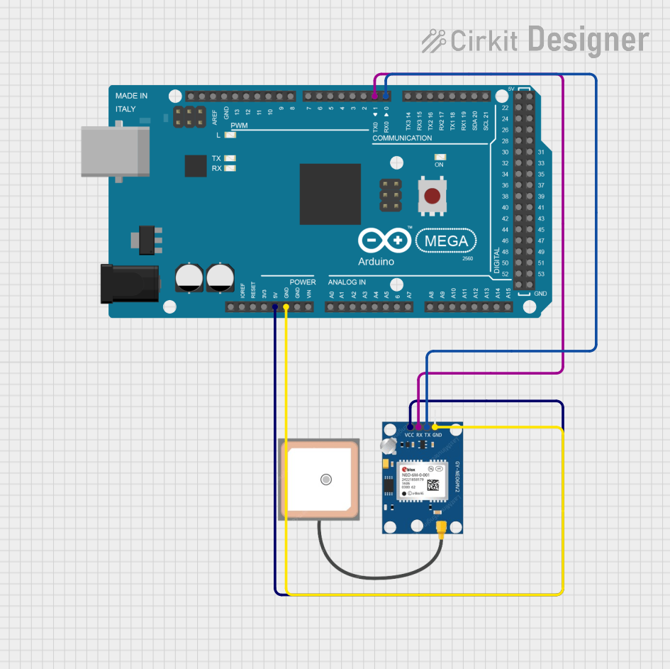
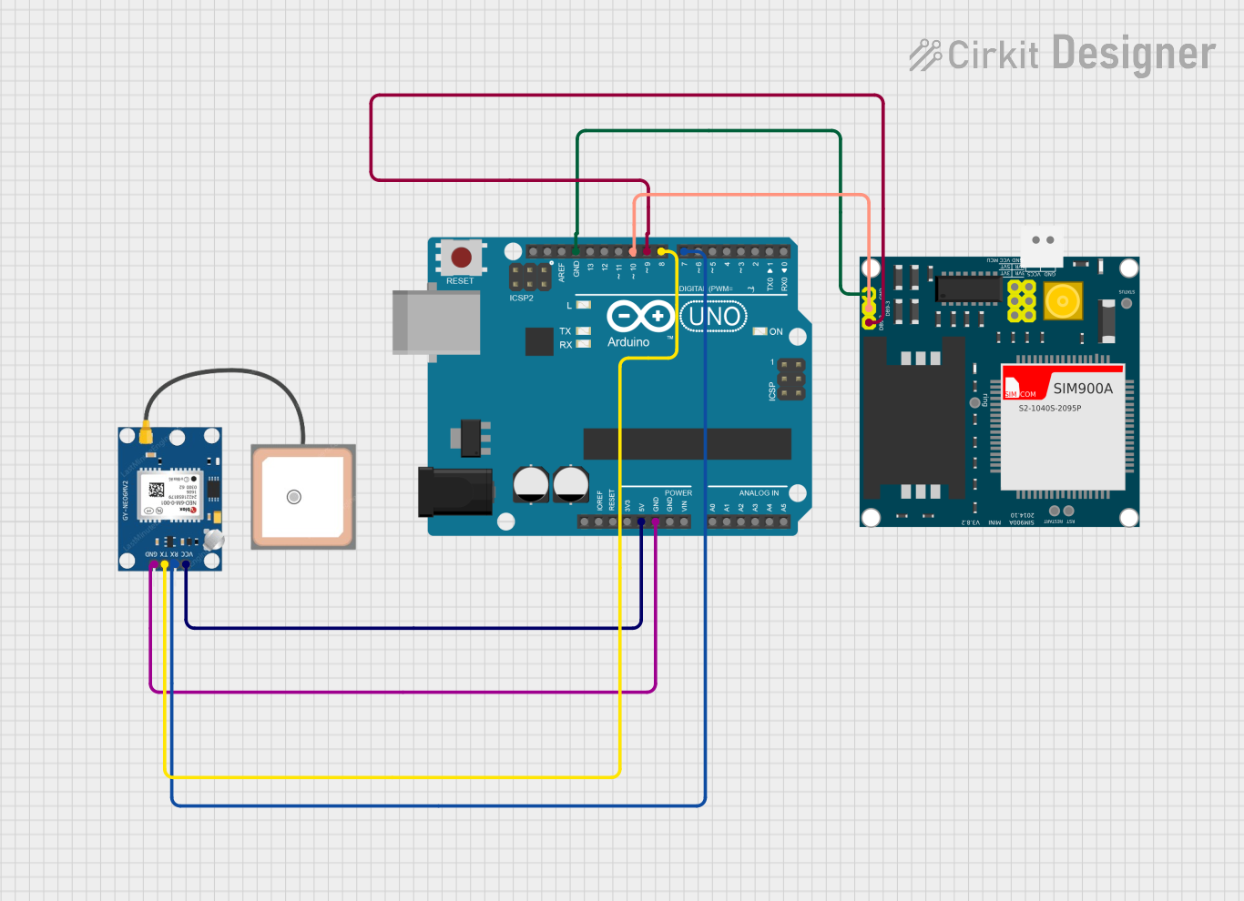
  1. Power Connection: Connect the VCC pin to a 3.3V or 5V power supply and the GND pin to the ground.
  2. Data Connection: Connect the TX pin of the GPS module to the RX pin of the microcontroller and the RX pin to the TX pin.
  3. Antenna: Ensure the GPS antenna is properly connected and has a clear view of the sky for optimal performance.

Important Considerations and Best Practices

  • Power Supply: Ensure that the power supply is stable and within the specified voltage range.
  • Antenna Placement: Place the antenna in a location with minimal obstructions to the sky.
  • Baud Rate: The default baud rate is 9600 bps. Make sure your microcontroller's serial port is set to this baud rate.
  • Cold Start: Allow time for the module to acquire satellite signals during the initial power-up (cold start).

Example Code for Arduino UNO

#include <SoftwareSerial.h>

// The GPS module's TX pin is connected to Arduino pin 4 (RX)
// The GPS module's RX pin is connected to Arduino pin 3 (TX)
SoftwareSerial gpsSerial(4, 3); // RX, TX

void setup() {
  // Start the serial communication
  Serial.begin(9600);
  gpsSerial.begin(9600);
  Serial.println("GPS Module NEO-6M Test");
}

void loop() {
  // Check if data is available from the GPS module
  if (gpsSerial.available()) {
    // Read the incoming byte from the GPS module
    char c = gpsSerial.read();
    // Print the incoming byte to the Serial Monitor
    Serial.write(c);
  }
}

Troubleshooting and FAQs

Common Issues Users Might Face

  • No Signal: If the module is not getting a signal, ensure that the antenna has a clear view of the sky and that the module is not indoors or near tall buildings.
  • Incorrect Baud Rate: If there is no data output, check that the baud rate of the GPS module and the microcontroller's serial port match.
  • No Power: Verify that the power connections are secure and the power supply is within the specified voltage range.

Solutions and Tips for Troubleshooting

  • Antenna Placement: Relocate the antenna or the entire module to a position with a better view of the sky.
  • Reset the Module: Power cycle the module to reset it and allow it to perform a new cold start.
  • Check Connections: Ensure all connections are secure and correct, especially the TX and RX pins.

FAQs

Q: How long does it take for the GPS module to get a fix? A: It can take up to 27 seconds for a cold start and 1 second for a hot start.

Q: Can I use the GPS module indoors? A: GPS signals are weak indoors and may not be sufficient for a reliable fix. It's recommended to use the module outdoors.

Q: What is the purpose of the PPS pin? A: The PPS pin outputs a pulse per second, which can be used for precise timekeeping or to synchronize multiple systems.

Q: How can I improve the accuracy of the GPS module? A: Ensure clear sky visibility, avoid interference sources, and allow sufficient time for the module to stabilize after power-up.