
How to Use Stepdown YX-3606: Examples, Pinouts, and Specs
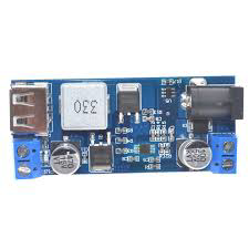
 Design with Stepdown YX-3606 in Cirkit Designer
Introduction
The Stepdown YX-3606 is a DC-DC buck converter designed to step down a higher input voltage to a stable, lower output voltage. This component is widely used in power supply circuits to provide a regulated voltage for microcontrollers, sensors, and other electronic devices. Its compact design and high efficiency make it ideal for battery-powered systems, embedded applications, and DIY electronics projects.
Explore Projects Built with Stepdown YX-3606
 Open Project in Cirkit Designer
 Open Project in Cirkit Designer
 Open Project in Cirkit Designer
 Open Project in Cirkit Designer
Explore Projects Built with Stepdown YX-3606
Open Project in Cirkit DesignerOpen Project in Cirkit DesignerOpen Project in Cirkit DesignerOpen Project in Cirkit DesignerCommon Applications
- Powering microcontrollers (e.g., Arduino, Raspberry Pi)
- Battery-powered devices
- Voltage regulation for sensors and modules
- DIY electronics and prototyping
- Industrial control systems
Technical Specifications
The following table outlines the key technical details of the Stepdown YX-3606:
| Parameter | Specification |
|---|---|
| Input Voltage Range | 4.5V to 40V |
| Output Voltage Range | 1.25V to 37V (adjustable) |
| Maximum Output Current | 3A (with proper heat dissipation) |
| Efficiency | Up to 92% |
| Switching Frequency | 150 kHz |
| Operating Temperature | -40°C to +85°C |
| Dimensions | 43mm x 21mm x 14mm |
Pin Configuration
The Stepdown YX-3606 has the following pin layout:
| Pin Name | Description |
|---|---|
| VIN | Input voltage (connect to power source) |
| VOUT | Regulated output voltage |
| GND | Ground (common for input and output) |
| ADJ | Voltage adjustment pin (connected to a potentiometer or resistor divider) |
Usage Instructions
How to Use the Stepdown YX-3606 in a Circuit
Connect the Input Voltage (VIN):
Attach the positive terminal of your power source to the VIN pin and the negative terminal to the GND pin. Ensure the input voltage is within the specified range (4.5V to 40V).Connect the Output Load (VOUT):
Connect the positive terminal of your load to the VOUT pin and the negative terminal to the GND pin.Adjust the Output Voltage:
Use the onboard potentiometer or an external resistor divider connected to the ADJ pin to set the desired output voltage. Measure the output voltage with a multimeter to ensure accuracy.Heat Dissipation:
If the load current exceeds 2A, attach a heatsink to the YX-3606 to prevent overheating and ensure stable operation.
Important Considerations
- Input Voltage: Always ensure the input voltage is higher than the desired output voltage by at least 1.5V for proper regulation.
- Current Limitation: Do not exceed the maximum output current of 3A. Use a heatsink for high-current applications.
- Capacitors: Add input and output capacitors (e.g., 10µF to 100µF) close to the VIN and VOUT pins to reduce voltage ripple and improve stability.
- Polarity: Double-check the polarity of your connections to avoid damaging the module.
Example: Using the YX-3606 with an Arduino UNO
The Stepdown YX-3606 can be used to power an Arduino UNO from a 12V power source. Here's how to connect it:
- Connect the 12V power source to the VIN and GND pins of the YX-3606.
- Adjust the output voltage to 5V using the potentiometer.
- Connect the VOUT pin to the 5V pin of the Arduino UNO and the GND pin to the Arduino's GND.
Sample Arduino Code
Below is an example code to blink an LED connected to the Arduino UNO powered by the YX-3606:
// Blink an LED connected to pin 13 of the Arduino UNO
// Ensure the YX-3606 is providing a stable 5V to the Arduino

void setup() {
  pinMode(13, OUTPUT); // Set pin 13 as an output
}

void loop() {
  digitalWrite(13, HIGH); // Turn the LED on
  delay(1000);            // Wait for 1 second
  digitalWrite(13, LOW);  // Turn the LED off
  delay(1000);            // Wait for 1 second
}
Troubleshooting and FAQs
Common Issues
No Output Voltage:
- Cause: Incorrect wiring or insufficient input voltage.
- Solution: Verify the connections and ensure the input voltage is within the specified range.
Output Voltage is Unstable:
- Cause: Missing or insufficient input/output capacitors.
- Solution: Add capacitors (e.g., 10µF to 100µF) close to the VIN and VOUT pins.
Overheating:
- Cause: High load current or poor heat dissipation.
- Solution: Attach a heatsink to the module and ensure proper ventilation.
Cannot Adjust Output Voltage:
- Cause: Faulty potentiometer or incorrect adjustment.
- Solution: Check the potentiometer and replace it if necessary. Ensure the ADJ pin is properly connected.
FAQs
Q: Can the YX-3606 step up voltage?
A: No, the YX-3606 is a buck converter and can only step down voltage.
Q: What is the minimum voltage difference between input and output?
A: The input voltage must be at least 1.5V higher than the desired output voltage.
Q: Can I use the YX-3606 with a battery?
A: Yes, the YX-3606 is suitable for battery-powered applications as long as the input voltage is within the specified range.
Q: How do I calculate the resistor values for the ADJ pin?
A: Use the formula:
[
V_{OUT} = 1.25 \times \left(1 + \frac{R_2}{R_1}\right)
]
where (R_1) and (R_2) are the resistors in the voltage divider network.
By following this documentation, you can effectively use the Stepdown YX-3606 in your projects and troubleshoot common issues.