
How to Use S1133 Si Photodiode: Examples, Pinouts, and Specs

 Design with S1133 Si Photodiode in Cirkit Designer
Introduction
The S1133 Si Photodiode, manufactured by Hamamatsu Photonics, is a silicon-based light sensor designed to convert light into an electrical current. It is highly sensitive to a broad spectrum of wavelengths, ranging from ultraviolet to near-infrared, making it an ideal choice for applications requiring precise optical detection and measurement. Its compact size and high reliability make it suitable for use in industrial, scientific, and consumer electronics.
Explore Projects Built with S1133 Si Photodiode
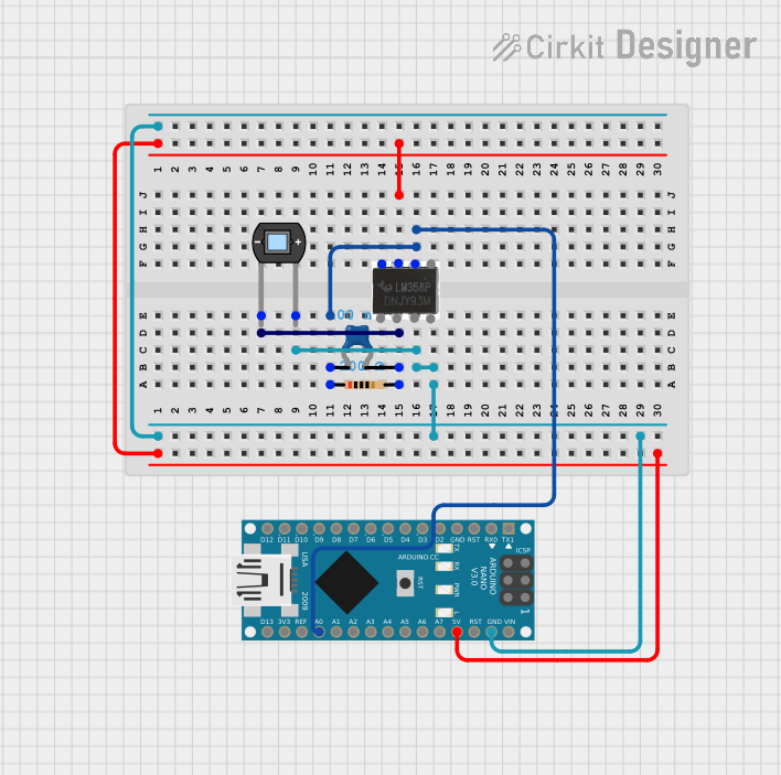 Open Project in Cirkit Designer
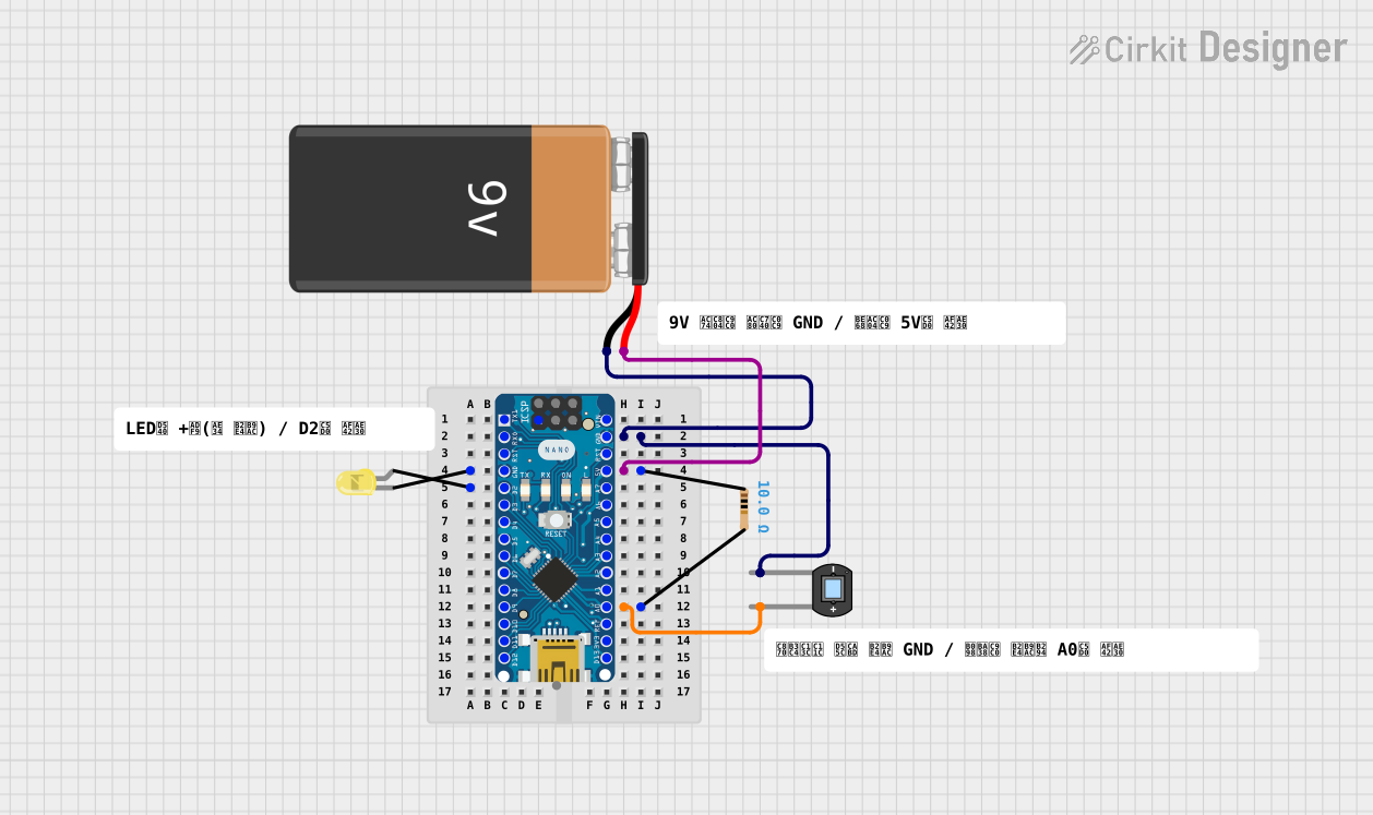 Open Project in Cirkit Designer
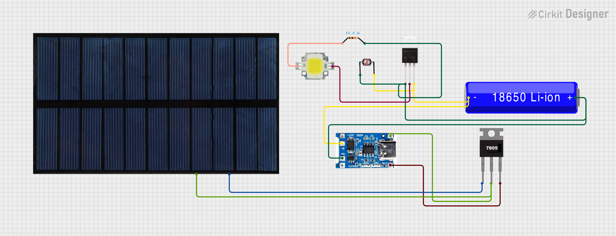 Open Project in Cirkit Designer
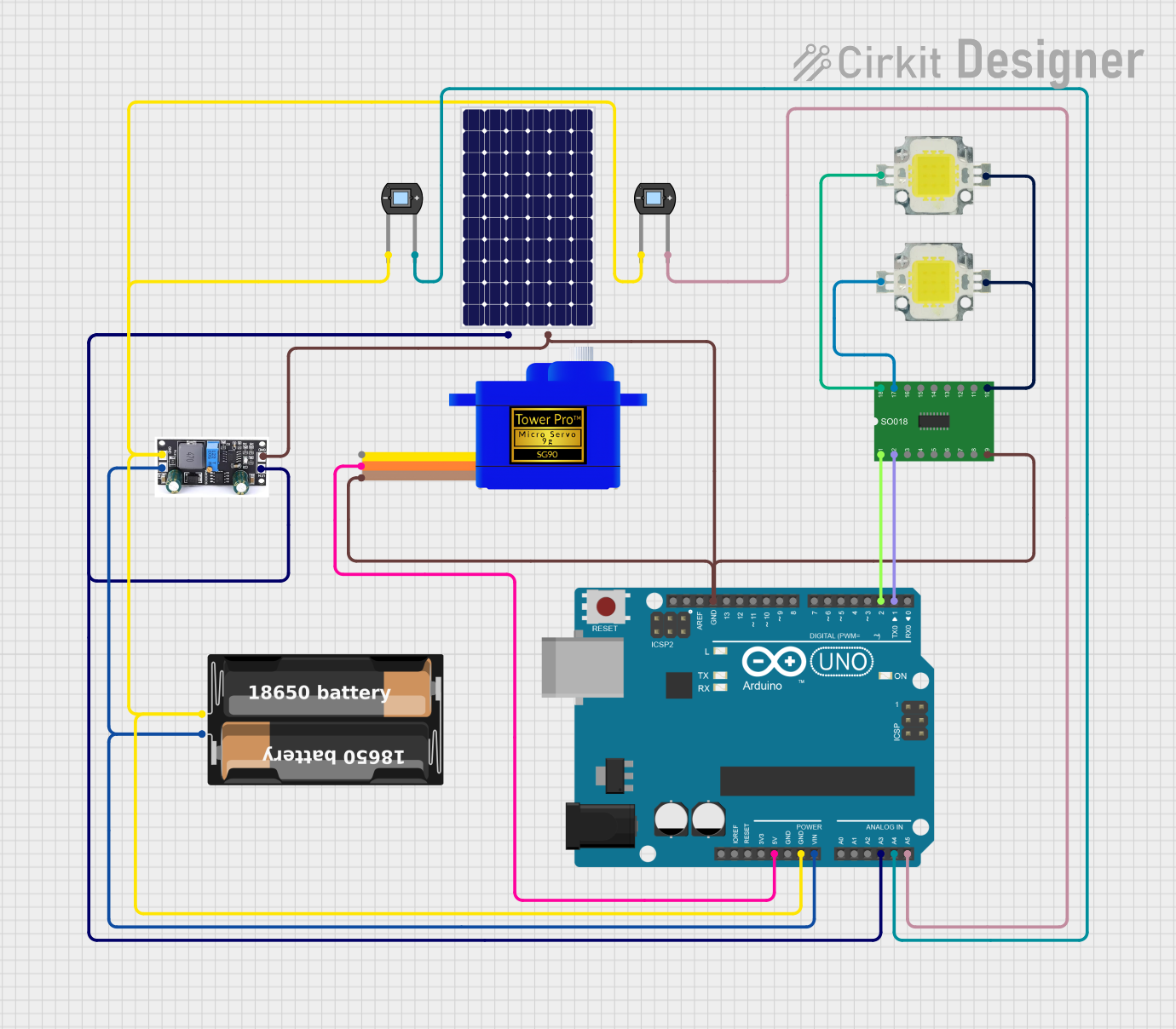 Open Project in Cirkit Designer
Explore Projects Built with S1133 Si Photodiode
Open Project in Cirkit DesignerOpen Project in Cirkit DesignerOpen Project in Cirkit DesignerOpen Project in Cirkit DesignerCommon Applications
- Optical power meters
- Light intensity measurement
- Spectrophotometry
- Flame detection systems
- Medical devices (e.g., pulse oximeters)
- Environmental monitoring (e.g., UV detection)
Technical Specifications
Key Technical Details
| Parameter | Value |
|---|---|
| Manufacturer Part ID | S1133 |
| Manufacturer | Hamamatsu Photonics |
| Spectral Response Range | 190 nm to 1100 nm |
| Peak Sensitivity Wavelength | 960 nm |
| Photosensitivity | 0.5 A/W (at 960 nm) |
| Active Area | 1.2 mm × 1.2 mm |
| Reverse Voltage (Max) | 10 V |
| Dark Current (at 10 V) | 2 nA (typical) |
| Capacitance (at 0 V) | 10 pF (typical) |
| Rise Time | 0.1 µs (typical) |
| Package Type | TO-18 metal can |
Pin Configuration and Descriptions
The S1133 Si Photodiode has two pins, as described below:
| Pin Number | Pin Name | Description |
|---|---|---|
| 1 | Anode | Positive terminal of the photodiode. Connect to the input of the circuit. |
| 2 | Cathode | Negative terminal of the photodiode. Typically connected to ground. |
Usage Instructions
How to Use the S1133 Si Photodiode in a Circuit
Basic Circuit Connection:
- Connect the anode (Pin 1) to the positive input of your circuit.
- Connect the cathode (Pin 2) to ground.
- Use a load resistor in series with the photodiode to convert the photocurrent into a measurable voltage.
Power Supply:
- The photodiode operates in reverse bias mode for enhanced performance. Apply a reverse voltage (up to 10 V) across the photodiode for optimal sensitivity and response time.
Signal Amplification:
- The output current from the photodiode is typically small. Use an operational amplifier (op-amp) in a transimpedance configuration to amplify the signal.
Wavelength Considerations:
- Ensure the light source falls within the photodiode's spectral response range (190 nm to 1100 nm) for accurate detection.
Important Considerations and Best Practices
- Avoid Overvoltage: Do not exceed the maximum reverse voltage of 10 V to prevent damage to the photodiode.
- Minimize Noise: Use proper shielding and grounding techniques to reduce electrical noise in the circuit.
- Temperature Stability: Operate the photodiode within the recommended temperature range to maintain performance.
- Light Saturation: Avoid exposing the photodiode to excessively high light intensities, which can saturate the output signal.
Example: Connecting the S1133 to an Arduino UNO
The following example demonstrates how to use the S1133 Si Photodiode with an Arduino UNO to measure light intensity.
Circuit Diagram
- Connect the anode of the photodiode to an analog input pin (e.g., A0) on the Arduino.
- Connect the cathode to ground.
- Place a 10 kΩ resistor between the anode and ground to act as a load resistor.
Arduino Code
// S1133 Si Photodiode Example with Arduino UNO
// This code reads the voltage across the photodiode and prints the light intensity
// to the Serial Monitor.

const int photodiodePin = A0; // Analog pin connected to the photodiode anode
int sensorValue = 0;          // Variable to store the analog reading

void setup() {
  Serial.begin(9600); // Initialize serial communication at 9600 baud
}

void loop() {
  sensorValue = analogRead(photodiodePin); // Read the analog value from the photodiode
  float voltage = sensorValue * (5.0 / 1023.0); // Convert the reading to voltage

  // Print the voltage to the Serial Monitor
  Serial.print("Photodiode Voltage: ");
  Serial.print(voltage);
  Serial.println(" V");

  delay(500); // Wait for 500 ms before the next reading
}
Troubleshooting and FAQs
Common Issues and Solutions
No Output Signal:
- Cause: Incorrect wiring or insufficient light intensity.
- Solution: Verify the connections and ensure the photodiode is exposed to a light source within its spectral range.
High Noise in Output:
- Cause: Electrical interference or improper grounding.
- Solution: Use shielded cables and ensure proper grounding of the circuit.
Saturated Output:
- Cause: Excessive light intensity.
- Solution: Reduce the light intensity or use an optical filter to limit the incoming light.
Slow Response Time:
- Cause: High capacitance or insufficient reverse bias voltage.
- Solution: Apply a reverse bias voltage (up to 10 V) to improve response time.
FAQs
Q1: Can the S1133 detect infrared light?
Yes, the S1133 is sensitive to near-infrared light, with a peak sensitivity at 960 nm.
Q2: What is the maximum operating temperature for the S1133?
The S1133 can operate within a temperature range of -30°C to +85°C.
Q3: Can I use the S1133 without a reverse bias voltage?
Yes, the photodiode can operate in photovoltaic mode (no bias), but its response time and sensitivity will be reduced.
Q4: How do I protect the photodiode from damage?
Avoid exceeding the maximum reverse voltage (10 V) and prevent exposure to excessive light intensities.
This concludes the documentation for the S1133 Si Photodiode. For further details, refer to the datasheet provided by Hamamatsu Photonics.