
How to Use EasyDriver_v44: Examples, Pinouts, and Specs
 Design with EasyDriver_v44 in Cirkit Designer
Introduction
The EasyDriver v44 (Manufacturer Part ID: ROB-10267) is a stepper motor driver module designed and manufactured by SparkFun Electronics. It provides an easy-to-use interface for controlling stepper motors with precision. The module supports adjustable current control and microstepping, making it suitable for a wide range of applications, including robotics, CNC machines, 3D printers, and other motion control systems.
The EasyDriver v44 is compatible with most stepper motors that operate between 7V and 30V and can be controlled using a microcontroller such as an Arduino. Its compact design and versatile features make it a popular choice for hobbyists and professionals alike.
Explore Projects Built with EasyDriver_v44
 Open Project in Cirkit Designer
 Open Project in Cirkit Designer
 Open Project in Cirkit Designer
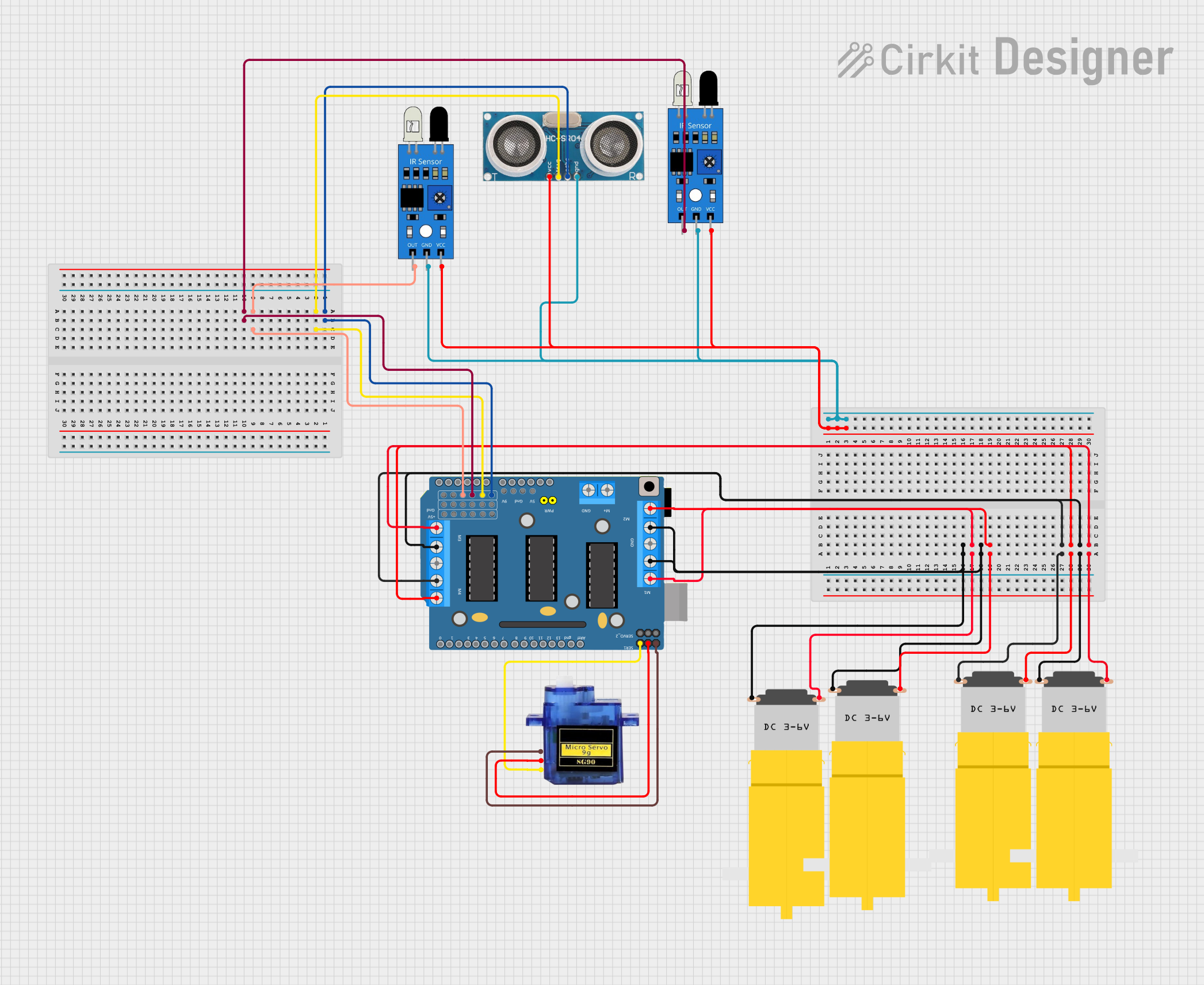 Open Project in Cirkit Designer
Explore Projects Built with EasyDriver_v44
Open Project in Cirkit DesignerOpen Project in Cirkit DesignerOpen Project in Cirkit DesignerOpen Project in Cirkit DesignerCommon Applications
- Robotics and automation systems
- CNC machines and 3D printers
- Camera sliders and gimbals
- Precision positioning systems
- Educational projects involving stepper motors
Technical Specifications
Key Technical Details
| Parameter | Value |
|---|---|
| Input Voltage Range | 7V to 30V DC |
| Output Current | Adjustable up to 750mA per phase |
| Microstepping Modes | Full, Half, Quarter, and Eighth steps |
| Logic Voltage | 3.3V or 5V (compatible with most MCUs) |
| Stepper Motor Type | Bipolar stepper motors |
| Driver IC | Allegro A3967 |
| Dimensions | 1.2" x 0.8" (30.5mm x 20.3mm) |
Pin Configuration and Descriptions
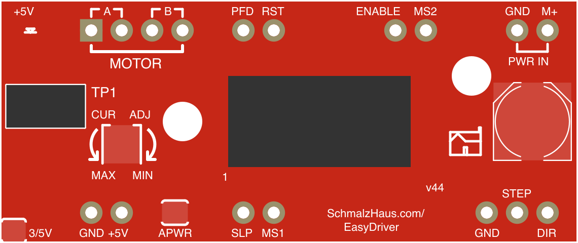
The EasyDriver v44 has a total of 14 pins. Below is the pinout and description:
| Pin Name | Type | Description |
|---|---|---|
| GND | Power | Ground connection for the module |
| M+ | Power | Motor power supply input (7V to 30V DC) |
| A and A̅ | Output | Connect to one coil of the stepper motor |
| B and B̅ | Output | Connect to the other coil of the stepper motor |
| STEP | Input | Pulse input to control the motor steps |
| DIR | Input | Direction control input (HIGH or LOW) |
| ENABLE | Input | Enables or disables the motor driver (LOW to enable, HIGH to disable) |
| MS1, MS2 | Input | Microstepping mode selection (see table below) |
| RST | Input | Resets the driver (active LOW) |
| SLP | Input | Sleep mode control (active LOW) |
| GND (Logic) | Power | Ground connection for logic signals |
| 5V | Power | Logic voltage input (3.3V or 5V) |
Microstepping Mode Selection
| MS1 | MS2 | Microstepping Mode |
|---|---|---|
| LOW | LOW | Full Step |
| HIGH | LOW | Half Step |
| LOW | HIGH | Quarter Step |
| HIGH | HIGH | Eighth Step |
Usage Instructions
How to Use the EasyDriver v44 in a Circuit
- Power Supply: Connect a DC power supply (7V to 30V) to the
M+andGNDpins. Ensure the power supply can provide sufficient current for your stepper motor. - Stepper Motor Connection: Connect the stepper motor coils to the
A,A̅,B, andB̅pins. Refer to your motor's datasheet to identify the coil pairs. - Microcontroller Interface: Connect the
STEPandDIRpins to the corresponding digital output pins of your microcontroller (e.g., Arduino). - Logic Voltage: Provide 3.3V or 5V to the
5Vpin to power the logic circuitry. - Microstepping Configuration: Set the
MS1andMS2pins to the desired logic levels to configure the microstepping mode. - Enable/Disable: Use the
ENABLEpin to enable or disable the driver. Pull it LOW to enable the motor driver.
Example Arduino Code
Below is an example of how to control a stepper motor using the EasyDriver v44 and an Arduino UNO:
// Define pin connections
const int stepPin = 3;  // Connect to the STEP pin on EasyDriver
const int dirPin = 4;   // Connect to the DIR pin on EasyDriver

void setup() {
  pinMode(stepPin, OUTPUT); // Set STEP pin as output
  pinMode(dirPin, OUTPUT);  // Set DIR pin as output

  digitalWrite(dirPin, HIGH); // Set initial direction (HIGH or LOW)
}

void loop() {
  // Rotate the motor one step at a time
  digitalWrite(stepPin, HIGH); // Generate a step pulse
  delayMicroseconds(1000);     // Wait for 1ms (adjust for speed control)
  digitalWrite(stepPin, LOW);  // End the step pulse
  delayMicroseconds(1000);     // Wait for 1ms before the next step
}
Important Considerations
- Current Adjustment: Use the onboard potentiometer to adjust the current limit for your stepper motor. Start with a low setting and gradually increase it while monitoring the motor's temperature.
- Heat Dissipation: The EasyDriver v44 may become warm during operation. Ensure proper ventilation or use a heatsink if necessary.
- Power Supply: Use a stable and adequately rated power supply to avoid voltage fluctuations that could damage the module or motor.
Troubleshooting and FAQs
Common Issues and Solutions
Motor Not Moving
- Cause: Incorrect wiring or insufficient power supply.
- Solution: Double-check the motor connections and ensure the power supply meets the voltage and current requirements.
Motor Vibrates but Does Not Rotate
- Cause: Incorrect coil connections.
- Solution: Verify the coil pairs using a multimeter and reconnect them correctly to the
A,A̅,B, andB̅pins.
Driver Overheating
- Cause: Excessive current setting or poor ventilation.
- Solution: Reduce the current limit using the potentiometer and ensure proper airflow around the module.
Stepper Motor Skipping Steps
- Cause: Step pulse frequency too high or insufficient current.
- Solution: Lower the step pulse frequency or increase the current limit slightly.
Microcontroller Not Communicating with EasyDriver
- Cause: Logic voltage mismatch or incorrect pin connections.
- Solution: Ensure the
5Vpin is connected to the correct logic voltage (3.3V or 5V) and verify theSTEPandDIRpin connections.
FAQs
Can the EasyDriver v44 drive unipolar stepper motors? No, the EasyDriver v44 is designed for bipolar stepper motors only.
What is the maximum step pulse frequency supported? The EasyDriver v44 can handle step pulse frequencies up to 500kHz.
Can I use the EasyDriver with a Raspberry Pi? Yes, the EasyDriver is compatible with the Raspberry Pi. Ensure proper logic level shifting if using 3.3V GPIO pins.
How do I reset the driver? Pull the
RSTpin LOW momentarily to reset the driver.
This concludes the documentation for the EasyDriver v44. For additional support, refer to the official SparkFun Electronics resources or community forums.