How to Use Phoenix Contact EV Charging Control Module: Examples, Pinouts, and Specs
Introduction
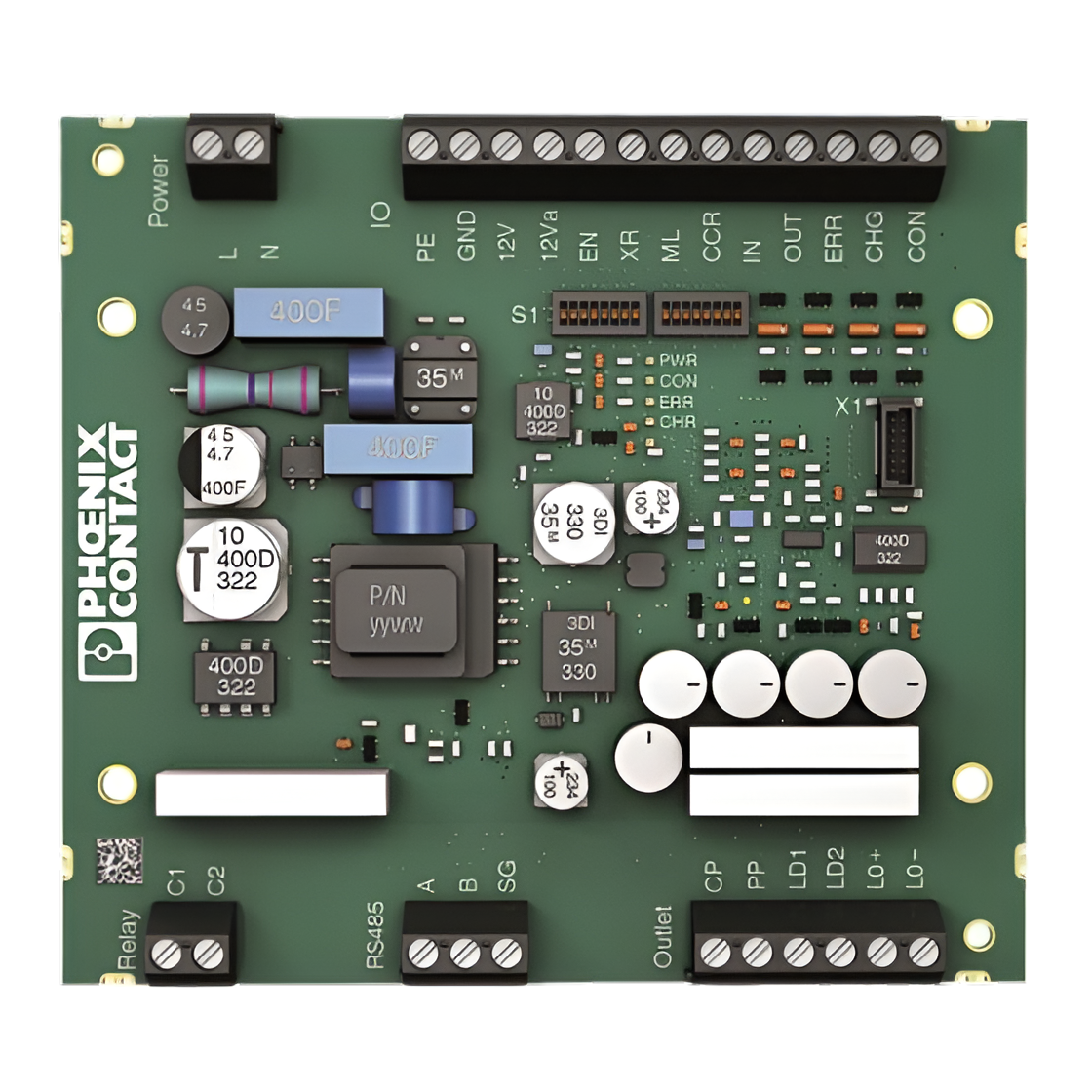
The Phoenix Contact EV Charging Control Module is a specialized electronic component designed to manage and control electric vehicle (EV) charging processes. It ensures safe and efficient power delivery while facilitating seamless communication between the EV and the charging infrastructure. This module is a critical component in modern EV charging stations, supporting compliance with international standards and protocols.
Explore Projects Built with Phoenix Contact EV Charging Control Module

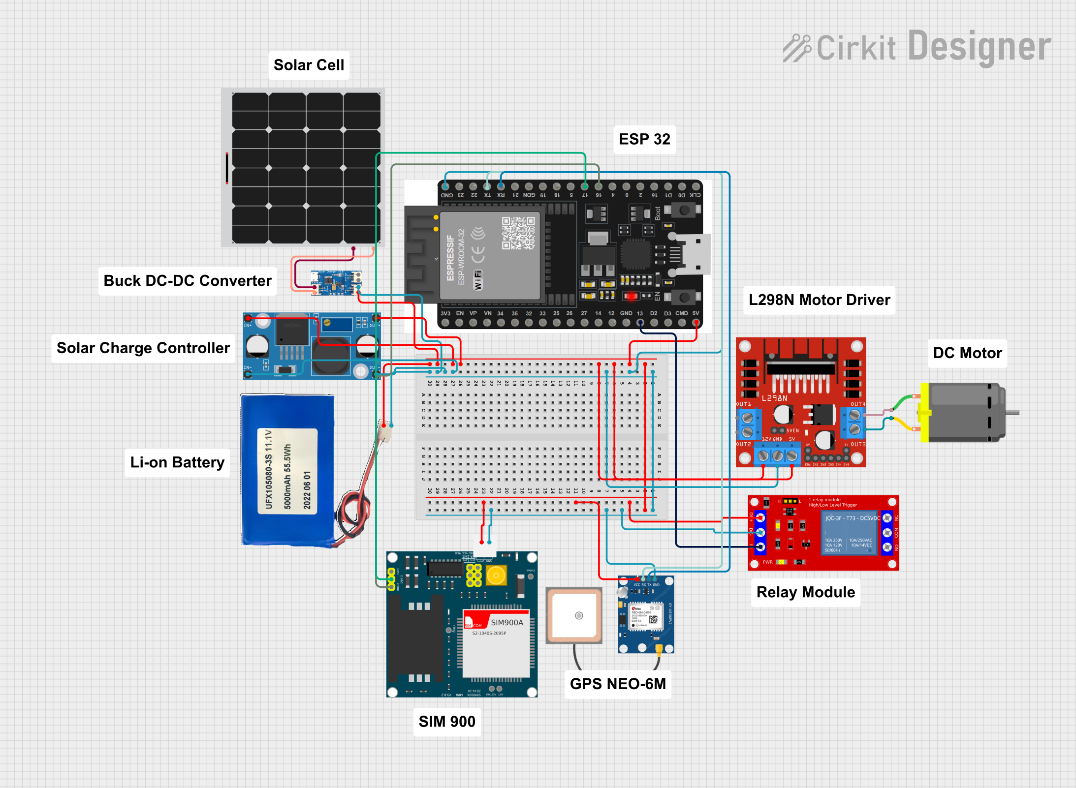
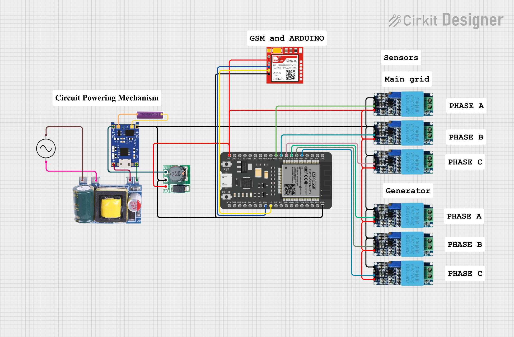
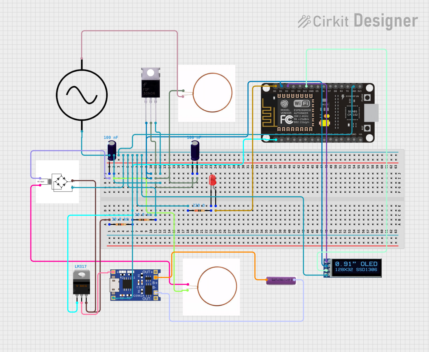
Explore Projects Built with Phoenix Contact EV Charging Control Module
Common Applications and Use Cases
- Public and private EV charging stations
- Residential EV chargers
- Commercial fleet charging systems
- Smart grid integration for energy management
- Fast-charging and DC charging stations
Technical Specifications
The Phoenix Contact EV Charging Control Module is engineered to meet the demanding requirements of EV charging systems. Below are its key technical specifications:
General Specifications
| Parameter | Value |
|---|---|
| Operating Voltage | 12 V DC / 24 V DC |
| Power Consumption | < 5 W |
| Communication Protocols | ISO 15118, OCPP, Modbus, CAN |
| Operating Temperature Range | -25°C to +70°C |
| Storage Temperature Range | -40°C to +85°C |
| Dimensions (L x W x H) | 100 mm x 75 mm x 30 mm |
| Mounting Type | DIN Rail |
Pin Configuration and Descriptions
| Pin Number | Pin Name | Description |
|---|---|---|
| 1 | GND | Ground connection for the module |
| 2 | VCC | Power supply input (12 V DC or 24 V DC) |
| 3 | CAN_H | CAN bus high line for communication |
| 4 | CAN_L | CAN bus low line for communication |
| 5 | CP (Control Pilot) | Signal line for communication with the EV (used for charging control) |
| 6 | PP (Proximity Pilot) | Signal line for detecting the presence of a connected EV plug |
| 7 | RS485_A | RS485 communication line A |
| 8 | RS485_B | RS485 communication line B |
| 9 | Relay Output 1 | Output for controlling external relays (e.g., contactors for power delivery) |
| 10 | Relay Output 2 | Additional relay output for auxiliary control |
Usage Instructions
How to Use the Component in a Circuit
- Power Supply: Connect the module to a stable 12 V DC or 24 V DC power source using the VCC and GND pins.
- Communication Setup:
- Use the CAN_H and CAN_L pins to connect the module to a CAN bus for communication with other system components.
- Alternatively, use the RS485_A and RS485_B pins for RS485-based communication.
- EV Detection:
- Connect the CP (Control Pilot) pin to the EV charging cable to enable communication with the vehicle.
- Use the PP (Proximity Pilot) pin to detect the presence of the EV plug.
- Relay Control: Use the relay output pins to control external relays or contactors for managing power delivery to the EV.
- Compliance with Standards: Ensure that the module is configured to comply with ISO 15118 or other relevant standards for EV charging.
Important Considerations and Best Practices
- Wiring: Use high-quality, shielded cables for communication lines to minimize interference.
- Grounding: Ensure proper grounding of the module to avoid electrical noise and ensure safety.
- Firmware Updates: Regularly update the module's firmware to maintain compatibility with the latest EVs and charging protocols.
- Overcurrent Protection: Use appropriate fuses or circuit breakers to protect the module and connected components.
- Testing: Test the system thoroughly after installation to ensure proper operation and compliance with safety standards.
Example Code for Arduino UNO Integration
The Phoenix Contact EV Charging Control Module can be integrated with an Arduino UNO for basic monitoring and control. Below is an example code snippet for reading the Control Pilot (CP) signal using an analog input pin:
// Example: Reading the Control Pilot (CP) signal from the EV Charging Control Module
const int cpPin = A0; // Connect the CP pin to Arduino analog pin A0

void setup() {
  Serial.begin(9600); // Initialize serial communication at 9600 baud
  pinMode(cpPin, INPUT); // Set the CP pin as an input
}

void loop() {
  int cpSignal = analogRead(cpPin); // Read the CP signal voltage
  float voltage = (cpSignal / 1023.0) * 5.0; // Convert to voltage (assuming 5V reference)

  // Print the CP signal voltage to the Serial Monitor
  Serial.print("Control Pilot Voltage: ");
  Serial.print(voltage);
  Serial.println(" V");

  delay(1000); // Wait for 1 second before the next reading
}
Note: Ensure that the CP signal voltage is within the Arduino's input voltage range (0-5 V). Use a voltage divider if necessary.
Troubleshooting and FAQs
Common Issues and Solutions
Module Not Powering On
- Cause: Incorrect power supply voltage or loose connections.
- Solution: Verify that the power supply voltage is within the specified range (12 V DC or 24 V DC). Check all connections.
No Communication with EV
- Cause: Faulty wiring or incorrect configuration.
- Solution: Check the CP and PP connections. Ensure that the module is configured to use the correct communication protocol (e.g., ISO 15118).
Relay Not Activating
- Cause: Incorrect relay wiring or insufficient control signal.
- Solution: Verify the relay connections and ensure that the control signal is being sent correctly.
Interference on Communication Lines
- Cause: Unshielded cables or improper grounding.
- Solution: Use shielded cables for communication lines and ensure proper grounding of the module.
FAQs
Q1: Can this module be used for DC fast charging?
Yes, the Phoenix Contact EV Charging Control Module supports DC fast charging when integrated with appropriate power electronics and communication systems.
Q2: Does the module support OCPP for backend communication?
Yes, the module supports OCPP (Open Charge Point Protocol) for communication with backend systems.
Q3: How do I update the firmware?
Firmware updates can be performed via the module's communication interface. Refer to the manufacturer's firmware update guide for detailed instructions.
Q4: Is the module compatible with all EVs?
The module is designed to comply with international standards (e.g., ISO 15118), ensuring compatibility with most EVs. However, always verify compatibility with specific vehicle models.