
How to Use Lt 1528: Examples, Pinouts, and Specs
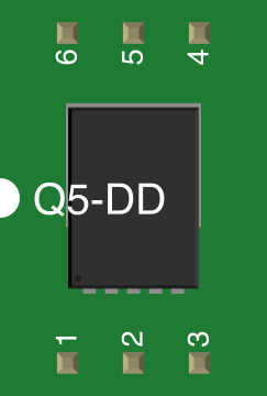
 Design with Lt 1528 in Cirkit Designer
Introduction
The LT1528 is a high-speed, precision voltage reference designed to deliver a stable output voltage with low noise and minimal drift. This component is ideal for high-performance analog applications where accuracy and stability are critical. Its robust design ensures reliable operation in demanding environments, making it a popular choice for use in data acquisition systems, precision measurement devices, and industrial control systems.
Explore Projects Built with Lt 1528
 Open Project in Cirkit Designer
 Open Project in Cirkit Designer
 Open Project in Cirkit Designer
 Open Project in Cirkit Designer
Explore Projects Built with Lt 1528
Open Project in Cirkit DesignerOpen Project in Cirkit DesignerOpen Project in Cirkit DesignerOpen Project in Cirkit DesignerCommon Applications
- Data acquisition systems
- Precision measurement instruments
- Industrial control systems
- High-resolution analog-to-digital converters (ADCs)
- Test and measurement equipment
Technical Specifications
The LT1528 is engineered to provide exceptional performance in a compact package. Below are its key technical specifications:
Key Parameters
| Parameter | Value |
|---|---|
| Output Voltage | 2.5V, 5V, or adjustable |
| Output Current | Up to 3A |
| Input Voltage Range | 3.6V to 20V |
| Line Regulation | 0.015%/V (typical) |
| Load Regulation | 0.05% (typical) |
| Temperature Coefficient | 20 ppm/°C (typical) |
| Noise (10Hz to 10kHz) | 20µV RMS |
| Operating Temperature | -40°C to 125°C |
| Package Options | TO-220, DD-Pak, SOT-223 |
Pin Configuration
The LT1528 is available in multiple package types. Below is the pin configuration for the TO-220 package:
| Pin Number | Pin Name | Description |
|---|---|---|
| 1 | VIN | Input voltage pin (3.6V to 20V) |
| 2 | GND | Ground pin |
| 3 | VOUT | Regulated output voltage |
| 4 | ADJ | Adjustment pin for setting output voltage |
For other package types, refer to the manufacturer's datasheet for detailed pin configurations.
Usage Instructions
The LT1528 is straightforward to use in a circuit. Below are the steps and considerations for integrating it into your design:
Basic Circuit Configuration
To use the LT1528 as a fixed voltage regulator:
- Connect the VIN pin to the input voltage source (ensure it is within the specified range of 3.6V to 20V).
- Connect the GND pin to the ground of the circuit.
- Connect the VOUT pin to the load or circuit requiring the regulated voltage.
- If using the adjustable version, connect a resistor divider network to the ADJ pin to set the desired output voltage.
Important Considerations
- Input Capacitor: Place a low-ESR capacitor (e.g., 10µF) close to the VIN pin to ensure stability and reduce input noise.
- Output Capacitor: Use a capacitor (e.g., 22µF) on the VOUT pin to maintain stability and minimize output noise.
- Thermal Management: If operating at high currents, ensure proper heat dissipation using a heatsink or adequate PCB thermal design.
- Adjustable Version: For the adjustable version, calculate the output voltage using the formula: [ V_{OUT} = V_{REF} \times \left(1 + \frac{R1}{R2}\right) ] where ( V_{REF} ) is the reference voltage (1.25V typical), and ( R1 ) and ( R2 ) are the resistors in the divider network.
Example: Using LT1528 with Arduino UNO
The LT1528 can be used to provide a stable 5V supply to an Arduino UNO or other microcontrollers. Below is an example circuit and code to read the regulated voltage:
Circuit Diagram
- Connect the VIN pin of the LT1528 to a 12V DC power supply.
- Connect the VOUT pin to the 5V pin of the Arduino UNO.
- Connect the GND pin to the Arduino's ground.
Arduino Code
// Example code to read and display the regulated voltage from LT1528
const int voltagePin = A0; // Analog pin connected to LT1528 VOUT
float referenceVoltage = 5.0; // LT1528 output voltage (5V in this example)

void setup() {
  Serial.begin(9600); // Initialize serial communication
}

void loop() {
  int sensorValue = analogRead(voltagePin); // Read analog value
  // Convert the analog reading to voltage
  float voltage = (sensorValue / 1023.0) * referenceVoltage;

  // Print the voltage to the Serial Monitor
  Serial.print("Regulated Voltage: ");
  Serial.print(voltage);
  Serial.println(" V");

  delay(1000); // Wait for 1 second before the next reading
}
Best Practices
- Always verify the input voltage is within the specified range to avoid damage.
- Use appropriate decoupling capacitors to minimize noise and ensure stability.
- For adjustable configurations, use precision resistors to achieve accurate output voltage.
Troubleshooting and FAQs
Common Issues
Output Voltage is Incorrect
- Verify the input voltage is within the specified range.
- Check the resistor values in the adjustable configuration.
- Ensure the output capacitor is properly connected and has the correct value.
Excessive Heat Generation
- Ensure the component is not exceeding its maximum current rating.
- Use a heatsink or improve PCB thermal design for better heat dissipation.
Noise on Output Voltage
- Add or replace the output capacitor with a low-ESR capacitor.
- Ensure proper grounding and minimize noise on the input voltage.
FAQs
Q: Can the LT1528 be used with batteries?
A: Yes, the LT1528 can regulate voltage from a battery source as long as the input voltage is within the specified range (3.6V to 20V).
Q: What is the maximum output current of the LT1528?
A: The LT1528 can provide up to 3A of output current, depending on the input voltage and thermal conditions.
Q: How do I calculate the output voltage for the adjustable version?
A: Use the formula ( V_{OUT} = V_{REF} \times \left(1 + \frac{R1}{R2}\right) ), where ( V_{REF} ) is typically 1.25V.
By following this documentation, you can effectively integrate the LT1528 into your designs and troubleshoot common issues with ease.