
How to Use PICAXE-18: Examples, Pinouts, and Specs
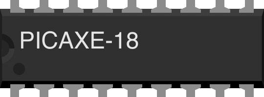
 Design with PICAXE-18 in Cirkit Designer
Introduction
The PICAXE-18 is an 8-bit microcontroller designed for educational and hobbyist projects. It is widely recognized for its simplicity and ease of use, making it an excellent choice for beginners and those new to microcontroller programming. The PICAXE-18 features built-in programming capabilities, eliminating the need for external programmers, and supports a BASIC-like programming language for rapid development.
This microcontroller is equipped with a variety of input/output pins, enabling seamless interfacing with sensors, actuators, and other electronic components. Its versatility and user-friendly nature make it suitable for applications such as robotics, home automation, data logging, and interactive projects.
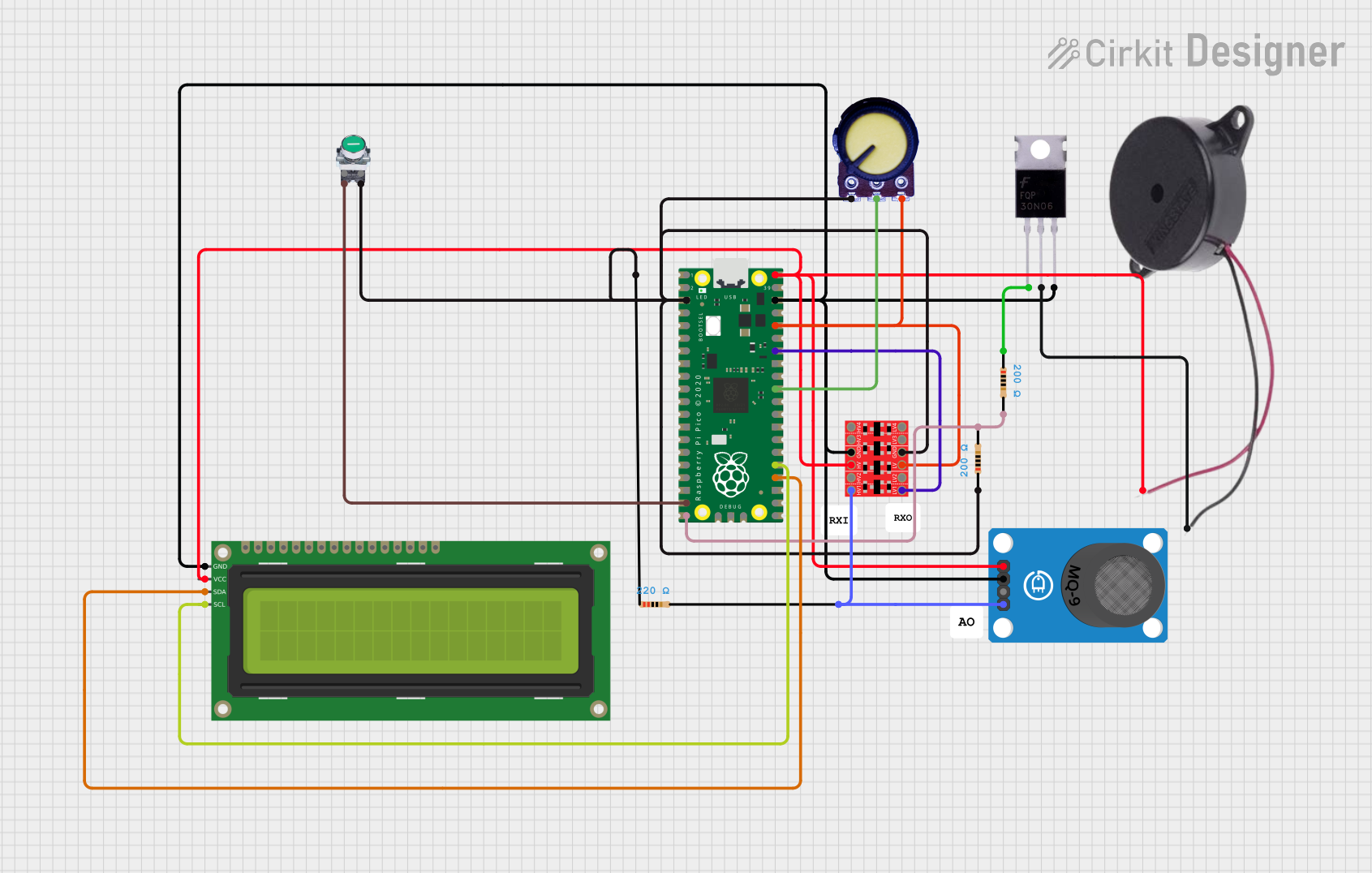
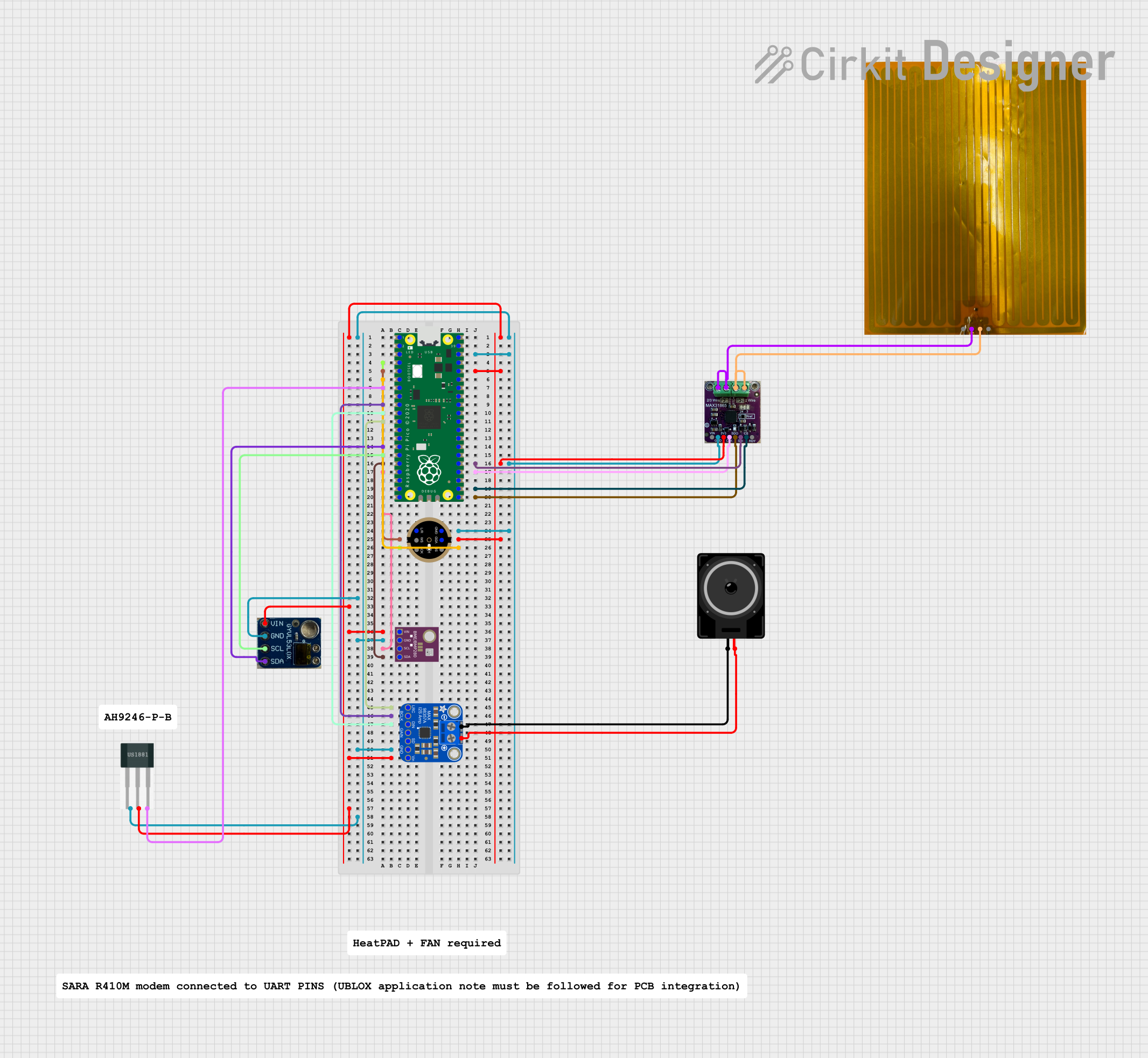
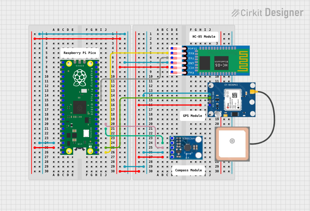
Explore Projects Built with PICAXE-18
 Open Project in Cirkit Designer
 Open Project in Cirkit Designer
 Open Project in Cirkit Designer
 Open Project in Cirkit Designer
Explore Projects Built with PICAXE-18
Open Project in Cirkit DesignerOpen Project in Cirkit DesignerOpen Project in Cirkit DesignerOpen Project in Cirkit DesignerTechnical Specifications
The following table outlines the key technical details of the PICAXE-18 microcontroller:
| Specification | Details |
|---|---|
| Architecture | 8-bit |
| Operating Voltage | 3V to 5V |
| Clock Speed | 4 MHz (internal oscillator) |
| Programming Language | BASIC-like (PICAXE Programming Editor) |
| Flash Memory | 2048 bytes |
| RAM | 256 bytes |
| EEPROM | 256 bytes |
| Number of I/O Pins | 8 digital I/O, 5 analog inputs |
| Communication Protocols | Serial (via programming cable) |
| Package Type | DIP-18 |
Pin Configuration and Descriptions
The PICAXE-18 has 18 pins, each with specific functions. The table below provides a detailed description of each pin:
| Pin Number | Pin Name | Function |
|---|---|---|
| 1 | VSS | Ground (0V) |
| 2 | Serial In | Serial programming input |
| 3 | Serial Out | Serial programming output |
| 4 | Input 3 | Digital/Analog input |
| 5 | Input 2 | Digital/Analog input |
| 6 | Input 1 | Digital/Analog input |
| 7 | Input 0 | Digital/Analog input |
| 8 | VDD | Positive supply voltage (3V to 5V) |
| 9 | Output 0 | Digital output |
| 10 | Output 1 | Digital output |
| 11 | Output 2 | Digital output |
| 12 | Output 3 | Digital output |
| 13 | Output 4 | Digital output |
| 14 | Input 4 | Digital/Analog input |
| 15 | Reset | Active-low reset pin |
| 16 | Not Used | Reserved for internal use |
| 17 | Not Used | Reserved for internal use |
| 18 | Not Used | Reserved for internal use |
Usage Instructions
How to Use the PICAXE-18 in a Circuit
- Power Supply: Connect the VDD pin (pin 8) to a 3V-5V power source and the VSS pin (pin 1) to ground.
- Programming: Use the PICAXE programming cable to connect the Serial In (pin 2) and Serial Out (pin 3) pins to your computer. The PICAXE Programming Editor software is required to write and upload code.
- Input/Output Connections:
- Connect sensors to the input pins (pins 4-7, 14) for reading digital or analog signals.
- Connect actuators (e.g., LEDs, motors) to the output pins (pins 9-13) for controlling external devices.
- Reset: Optionally, connect a push-button to the Reset pin (pin 15) for manual resetting of the microcontroller.
Important Considerations and Best Practices
- Voltage Levels: Ensure the supply voltage is within the 3V-5V range to avoid damaging the microcontroller.
- Pull-Down Resistors: Use pull-down resistors on input pins to prevent floating inputs when no signal is connected.
- Programming Cable: Always disconnect the programming cable after uploading code to avoid interference during operation.
- Decoupling Capacitor: Place a 0.1 µF capacitor between VDD and VSS to stabilize the power supply.
Example Code for Arduino-like Functionality
Below is an example of a simple program to blink an LED connected to Output 0 (pin 9):
' Blink an LED connected to Output 0 (pin 9) of the PICAXE-18
' The LED will turn on for 1 second and off for 1 second in a loop.

main:                ' Define the main program loop
  high 0             ' Set Output 0 (pin 9) to HIGH (turn LED on)
  pause 1000         ' Wait for 1000 milliseconds (1 second)
  low 0              ' Set Output 0 (pin 9) to LOW (turn LED off)
  pause 1000         ' Wait for 1000 milliseconds (1 second)
  goto main          ' Repeat the loop
Troubleshooting and FAQs
Common Issues and Solutions
Microcontroller Not Responding to Programming:
- Ensure the programming cable is securely connected to the Serial In and Serial Out pins.
- Verify that the correct COM port is selected in the PICAXE Programming Editor.
- Check the power supply to ensure the microcontroller is powered.
Input Pins Not Reading Correctly:
- Use pull-down resistors to prevent floating inputs.
- Verify that the sensor or input device is functioning correctly.
Output Pins Not Driving Actuators:
- Ensure the connected device does not exceed the current rating of the output pins.
- Use external transistors or relays for high-current devices.
Microcontroller Resets Unexpectedly:
- Check for voltage fluctuations or noise in the power supply.
- Add a decoupling capacitor between VDD and VSS.
FAQs
Q: Can the PICAXE-18 handle PWM signals?
A: Yes, the PICAXE-18 supports PWM (Pulse Width Modulation) on certain output pins, which can be used for applications like motor speed control or LED dimming.
Q: Is the PICAXE-18 compatible with breadboards?
A: Yes, the PICAXE-18 comes in a DIP-18 package, making it easy to use with standard breadboards and prototyping boards.
Q: What software is required to program the PICAXE-18?
A: The PICAXE Programming Editor, available for free on the PICAXE website, is used to write and upload code to the microcontroller.
Q: Can I use the PICAXE-18 with external sensors?
A: Absolutely! The PICAXE-18 supports both digital and analog sensors, making it ideal for a wide range of applications.