How to Use ISOLATOR SWITCH: Examples, Pinouts, and Specs
Introduction
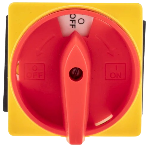
An isolator switch is a mechanical switch designed to completely de-energize an electrical circuit for maintenance, safety, or troubleshooting purposes. It provides a visible and reliable break in the circuit, ensuring that no current flows through the system when the switch is in the "off" position. Isolator switches are commonly used in high-voltage applications, industrial systems, and electrical distribution networks to protect personnel and equipment.
Explore Projects Built with ISOLATOR SWITCH


Explore Projects Built with ISOLATOR SWITCH
Common Applications and Use Cases
- Electrical maintenance and servicing in industrial plants
- High-voltage power distribution systems
- Solar power installations for isolating photovoltaic arrays
- Emergency power disconnection in critical systems
- Circuit isolation in motor control centers
Technical Specifications
Below are the key technical details for the ISOLATOR SWITCH:
General Specifications
| Parameter | Value |
|---|---|
| Manufacturer | ISOLATOR SWITCH |
| Manufacturer Part ID | ISOLATOR SWITCH |
| Rated Voltage | Up to 1000V AC/DC (varies by model) |
| Rated Current | 16A to 630A (varies by model) |
| Operating Temperature | -25°C to +55°C |
| Insulation Resistance | ≥ 10 MΩ |
| Mechanical Lifespan | 10,000 operations (typical) |
| Mounting Type | Panel-mounted or DIN rail |
| Enclosure Protection | IP20 to IP65 (depending on model) |
Pin Configuration and Descriptions
Isolator switches typically have terminals for input and output connections. Below is a general description of the terminal configuration:
| Terminal Label | Description |
|---|---|
| L1, L2, L3 | Input terminals for three-phase power lines |
| T1, T2, T3 | Output terminals for three-phase load lines |
| N | Neutral terminal (if applicable) |
| PE | Protective Earth terminal |
Note: The exact terminal configuration may vary depending on the specific model and application. Always refer to the manufacturer's datasheet for detailed information.
Usage Instructions
How to Use the ISOLATOR SWITCH in a Circuit
- Select the Appropriate Model: Choose an isolator switch rated for the voltage and current of your application.
- Mount the Switch: Install the switch on a panel or DIN rail as per the mounting instructions provided by the manufacturer.
- Connect the Terminals:
- Connect the input power lines (L1, L2, L3) to the corresponding input terminals.
- Connect the load lines (T1, T2, T3) to the output terminals.
- If applicable, connect the neutral (N) and protective earth (PE) terminals.
- Test the Installation:
- Ensure all connections are secure and properly tightened.
- Verify that the switch operates smoothly between the "on" and "off" positions.
- Operate the Switch:
- Turn the switch to the "off" position to isolate the circuit.
- Perform maintenance or troubleshooting as needed.
- Turn the switch back to the "on" position to restore power.
Important Considerations and Best Practices
- Safety First: Always ensure the isolator switch is in the "off" position before performing any maintenance or wiring.
- Proper Sizing: Use an isolator switch with a current and voltage rating that matches or exceeds the requirements of your circuit.
- Environmental Protection: For outdoor or harsh environments, use an isolator switch with an appropriate IP rating (e.g., IP65 for dust and water resistance).
- Regular Maintenance: Periodically inspect the switch for signs of wear, corrosion, or damage to ensure reliable operation.
Example: Connecting an Isolator Switch to an Arduino UNO
While isolator switches are not typically used directly with microcontrollers like the Arduino UNO, they can be part of a larger system where the Arduino controls a relay or contactor. Below is an example of how an Arduino can control a relay to operate a circuit that includes an isolator switch:
// Example: Arduino controlling a relay in a circuit with an isolator switch
// Ensure the isolator switch is in the "on" position for this example to work.

const int relayPin = 7; // Pin connected to the relay module

void setup() {
  pinMode(relayPin, OUTPUT); // Set the relay pin as an output
  digitalWrite(relayPin, LOW); // Start with the relay off
}

void loop() {
  // Turn the relay on (simulate closing the circuit)
  digitalWrite(relayPin, HIGH);
  delay(5000); // Keep the relay on for 5 seconds

  // Turn the relay off (simulate opening the circuit)
  digitalWrite(relayPin, LOW);
  delay(5000); // Keep the relay off for 5 seconds
}
Note: The isolator switch in this example is used as a manual safety device. The Arduino controls the relay, which can automate the circuit operation.
Troubleshooting and FAQs
Common Issues and Solutions
| Issue | Possible Cause | Solution |
|---|---|---|
| Switch does not operate smoothly | Mechanical wear or debris in the switch | Clean or replace the switch |
| Circuit remains energized when off | Incorrect wiring or faulty switch | Verify wiring and test the switch |
| Overheating of terminals | Loose connections or undersized switch | Tighten connections or use a larger switch |
FAQs
Can an isolator switch be used as an emergency stop?
- No, isolator switches are not designed for frequent operation or emergency stops. Use a dedicated emergency stop switch for such applications.
What is the difference between an isolator switch and a circuit breaker?
- An isolator switch provides a visible break in the circuit for safety and maintenance, while a circuit breaker automatically trips to protect against overcurrent or short circuits.
Can I use an isolator switch in a DC circuit?
- Yes, but ensure the isolator switch is rated for DC operation, as DC arcs are harder to extinguish than AC arcs.
How often should I inspect my isolator switch?
- Perform a visual inspection every 6-12 months and a detailed inspection during routine maintenance.
By following this documentation, users can safely and effectively use the ISOLATOR SWITCH in their electrical systems.