How to Use 3 AA battery pack: Examples, Pinouts, and Specs
Introduction
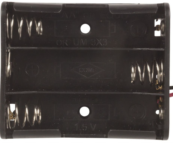
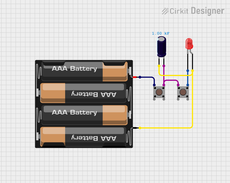
The 3 AA Battery Pack (Manufacturer: Arduino, Part ID: Battery Pack) is a compact and durable battery holder designed to house three AA batteries in series. This configuration provides a combined output voltage of 4.5V, making it ideal for powering small electronic devices, prototyping circuits, and portable projects. The battery pack is equipped with leads for easy connection to circuits and is compatible with a wide range of electronic components and microcontrollers.
Explore Projects Built with 3 AA battery pack
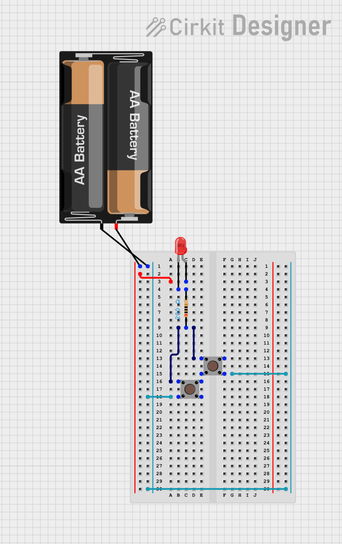
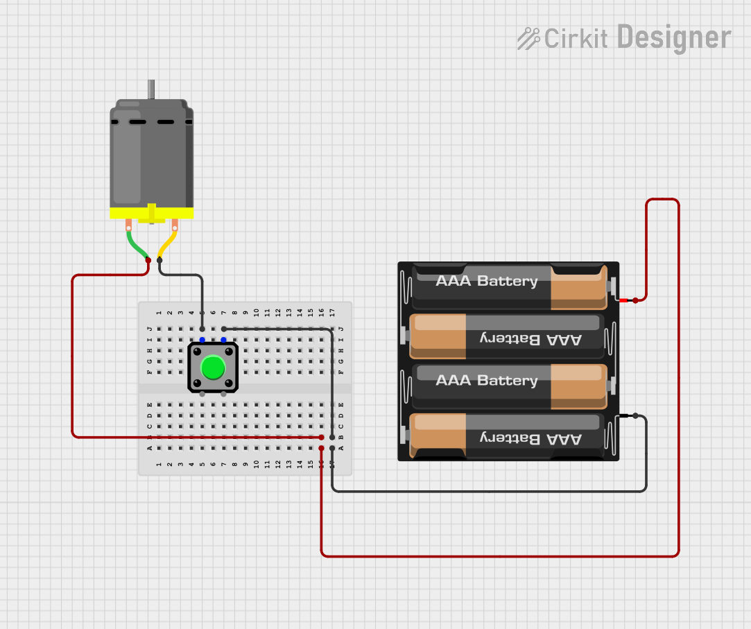
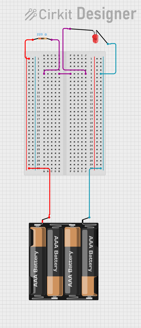
Explore Projects Built with 3 AA battery pack
Common Applications and Use Cases
- Powering small electronic devices such as sensors, motors, and LEDs.
- Supplying power to microcontrollers like Arduino boards in portable projects.
- Prototyping circuits where a stable 4.5V power source is required.
- Educational and DIY electronics projects.
Technical Specifications
The following table outlines the key technical details of the 3 AA Battery Pack:
| Specification | Details |
|---|---|
| Manufacturer | Arduino |
| Part ID | Battery Pack |
| Battery Type Supported | AA (1.5V each) |
| Output Voltage | 4.5V (3 x 1.5V in series) |
| Maximum Current | Dependent on battery capacity |
| Dimensions | 60mm x 45mm x 20mm (approx.) |
| Lead Length | 150mm (approx.) |
| Connector Type | Bare wire leads |
| Material | Durable plastic housing |
Pin Configuration and Descriptions
The 3 AA Battery Pack does not have traditional pins but includes two leads for connection:
| Lead | Color | Description |
|---|---|---|
| Positive | Red | Connects to the positive terminal of the circuit. |
| Negative | Black | Connects to the negative terminal (ground) of the circuit. |
Usage Instructions
How to Use the Component in a Circuit
- Insert Batteries: Place three AA batteries into the holder, ensuring correct polarity as indicated inside the battery pack.
- Connect Leads:
- Connect the red lead to the positive terminal of your circuit.
- Connect the black lead to the ground (negative terminal) of your circuit.
- Verify Voltage: Use a multimeter to confirm the output voltage is approximately 4.5V before connecting to sensitive components.
- Integrate with Circuit: Use the battery pack to power your circuit or microcontroller. For Arduino projects, connect the leads to the VIN (red lead) and GND (black lead) pins.
Important Considerations and Best Practices
- Battery Type: Use only 1.5V AA batteries (alkaline or rechargeable). Mixing battery types or voltages can damage the pack or connected devices.
- Polarity: Always double-check the polarity of the leads before connecting to a circuit to avoid damage.
- Current Draw: Ensure the total current draw of your circuit does not exceed the capacity of the batteries used.
- Secure Connections: Use soldering or secure connectors to prevent loose connections during operation.
- Power Regulation: If powering sensitive components, consider using a voltage regulator to ensure a stable 4.5V output.
Example: Connecting to an Arduino UNO
The 3 AA Battery Pack can be used to power an Arduino UNO. Below is an example of how to connect it:
- Connect the red lead of the battery pack to the VIN pin of the Arduino UNO.
- Connect the black lead of the battery pack to the GND pin of the Arduino UNO.
Sample Code
Here is a simple Arduino sketch to blink an LED using the 3 AA Battery Pack as the power source:
// This code blinks an LED connected to pin 13 of the Arduino UNO.
// Ensure the Arduino is powered by the 3 AA Battery Pack.

void setup() {
  pinMode(13, OUTPUT); // Set pin 13 as an output pin
}

void loop() {
  digitalWrite(13, HIGH); // Turn the LED on
  delay(1000);            // Wait for 1 second
  digitalWrite(13, LOW);  // Turn the LED off
  delay(1000);            // Wait for 1 second
}
Troubleshooting and FAQs
Common Issues Users Might Face
No Output Voltage:
- Cause: Batteries are inserted incorrectly or are depleted.
- Solution: Check the polarity of the batteries and replace them if necessary.
Loose Connections:
- Cause: Leads are not securely connected to the circuit.
- Solution: Use soldering or secure connectors to ensure a stable connection.
Overheating:
- Cause: Excessive current draw from the circuit.
- Solution: Ensure the circuit's current draw does not exceed the capacity of the batteries.
Voltage Drop:
- Cause: Batteries are nearing depletion or the circuit is drawing too much current.
- Solution: Replace the batteries or reduce the load on the circuit.
Solutions and Tips for Troubleshooting
- Always use fresh or fully charged batteries for optimal performance.
- Use a multimeter to verify the output voltage and troubleshoot connection issues.
- If the battery pack is not powering your circuit, check for corrosion on the battery terminals and clean them if necessary.
- Avoid shorting the leads of the battery pack, as this can damage the batteries and pose a safety hazard.
By following this documentation, you can effectively use the 3 AA Battery Pack in your electronic projects and ensure reliable performance.