Cirkit Designer Logo
Cirkit Designer
Your all-in-one circuit design IDE
Home / 
Component Documentation

How to Use XL4015 5A DC Buck Step-down: Examples, Pinouts, and Specs

Image of XL4015 5A DC Buck Step-down
Cirkit Designer LogoDesign with XL4015 5A DC Buck Step-down in Cirkit Designer

Introduction

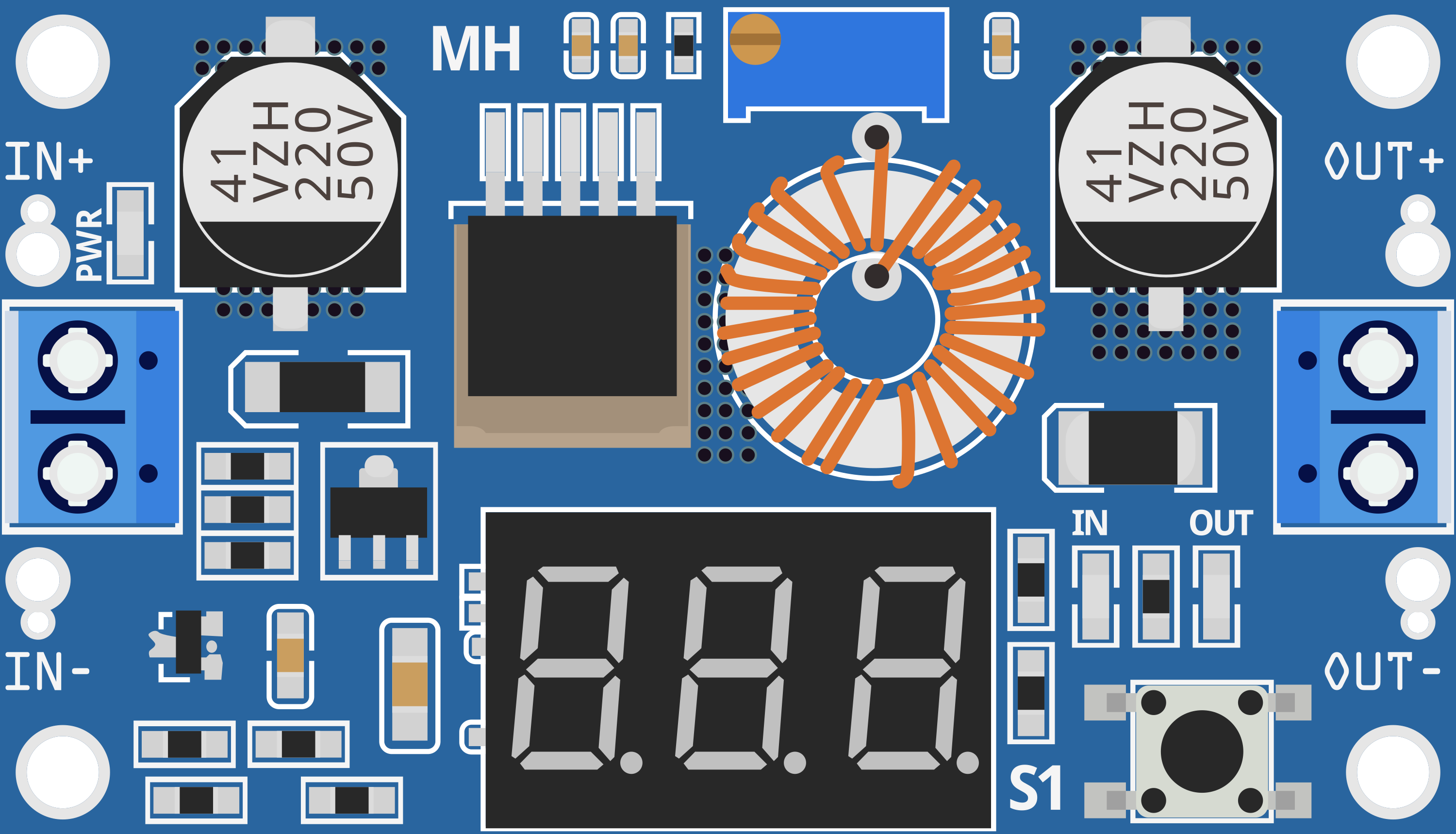
The XL4015 is a high-efficiency, step-down DC-DC converter module capable of handling up to 5A of current while maintaining a stable output voltage. This module is widely used in applications requiring voltage reduction from a higher voltage source to a lower voltage for various electronic devices, such as powering LEDs, battery charging, and as a power supply for embedded electronics.

Explore Projects Built with XL4015 5A DC Buck Step-down

Use Cirkit Designer to design, explore, and prototype these projects online. Some projects support real-time simulation. Click "Open Project" to start designing instantly!
Dual Motor Control Circuit with Directional Switching and Voltage Regulation
Image of Pencuci Kipas: A project utilizing XL4015 5A DC Buck Step-down in a practical application
This circuit features a 12V battery connected through a rocker switch to two buck converters, one of which steps down the voltage to power two DC mini metal gear motors, and the other is connected to a directional switch that controls a third DC mini metal gear motor. The XL4015 5A DC Buck Step-down converter's output is connected to two motors, allowing them to run at a reduced voltage, while the other buck converter's output is routed through a directional switch to control the direction of the third motor.
Cirkit Designer LogoOpen Project in Cirkit Designer
Battery-Powered DC Generator with XL4015 Buck Converter
Image of conveyor: A project utilizing XL4015 5A DC Buck Step-down in a practical application
This circuit consists of a 12V battery connected to a rocker switch, which controls the input to an XL4015 DC Buck Step-down converter. The converter steps down the voltage to power a DC generator, with the generator's output connected back to the converter to form a feedback loop.
Cirkit Designer LogoOpen Project in Cirkit Designer
Smart DC Motor Control System with Relay and Capacitive Sensors
Image of conveyor: A project utilizing XL4015 5A DC Buck Step-down in a practical application
This circuit controls two DC motors using a combination of relays, a toggle switch, and capacitive sensors. The XL4015 DC Buck Step-down module provides regulated power, while the capacitive sensors and toggle switch are used to control the relays, which in turn manage the operation of the motors.
Cirkit Designer LogoOpen Project in Cirkit Designer
Battery-Powered UPS with Step-Down Buck Converter and BMS
Image of Mini ups: A project utilizing XL4015 5A DC Buck Step-down in a practical application
This circuit is a power management system that steps down a 240V AC input to a lower DC voltage using a buck converter, which then powers a 40W UPS. The UPS is controlled by a rocker switch and is backed up by a battery management system (BMS) connected to three 3.7V batteries in series, ensuring continuous power supply.
Cirkit Designer LogoOpen Project in Cirkit Designer

Explore Projects Built with XL4015 5A DC Buck Step-down

Use Cirkit Designer to design, explore, and prototype these projects online. Some projects support real-time simulation. Click "Open Project" to start designing instantly!
Image of Pencuci Kipas: A project utilizing XL4015 5A DC Buck Step-down in a practical application
Dual Motor Control Circuit with Directional Switching and Voltage Regulation
This circuit features a 12V battery connected through a rocker switch to two buck converters, one of which steps down the voltage to power two DC mini metal gear motors, and the other is connected to a directional switch that controls a third DC mini metal gear motor. The XL4015 5A DC Buck Step-down converter's output is connected to two motors, allowing them to run at a reduced voltage, while the other buck converter's output is routed through a directional switch to control the direction of the third motor.
Cirkit Designer LogoOpen Project in Cirkit Designer
Image of conveyor: A project utilizing XL4015 5A DC Buck Step-down in a practical application
Battery-Powered DC Generator with XL4015 Buck Converter
This circuit consists of a 12V battery connected to a rocker switch, which controls the input to an XL4015 DC Buck Step-down converter. The converter steps down the voltage to power a DC generator, with the generator's output connected back to the converter to form a feedback loop.
Cirkit Designer LogoOpen Project in Cirkit Designer
Image of conveyor: A project utilizing XL4015 5A DC Buck Step-down in a practical application
Smart DC Motor Control System with Relay and Capacitive Sensors
This circuit controls two DC motors using a combination of relays, a toggle switch, and capacitive sensors. The XL4015 DC Buck Step-down module provides regulated power, while the capacitive sensors and toggle switch are used to control the relays, which in turn manage the operation of the motors.
Cirkit Designer LogoOpen Project in Cirkit Designer
Image of Mini ups: A project utilizing XL4015 5A DC Buck Step-down in a practical application
Battery-Powered UPS with Step-Down Buck Converter and BMS
This circuit is a power management system that steps down a 240V AC input to a lower DC voltage using a buck converter, which then powers a 40W UPS. The UPS is controlled by a rocker switch and is backed up by a battery management system (BMS) connected to three 3.7V batteries in series, ensuring continuous power supply.
Cirkit Designer LogoOpen Project in Cirkit Designer

Common Applications and Use Cases

  • LED drivers
  • Battery chargers
  • Power supplies for electronic devices
  • Solar power supplies
  • DIY electronics projects

Technical Specifications

Key Technical Details

  • Input Voltage Range: 4V to 38V DC
  • Output Voltage Range: 1.25V to 36V DC (adjustable via potentiometer)
  • Output Current: Up to 5A (with proper heat sinking)
  • Efficiency: Up to 96%
  • Switching Frequency: 180kHz
  • Operating Temperature: -40°C to +85°C

Pin Configuration and Descriptions

Pin Number Name Description
1 IN+ Input positive
2 IN- Input negative
3 OUT+ Output positive
4 OUT- Output negative
5 ADJ Adjustment potentiometer (built-in)

Usage Instructions

How to Use the Component in a Circuit

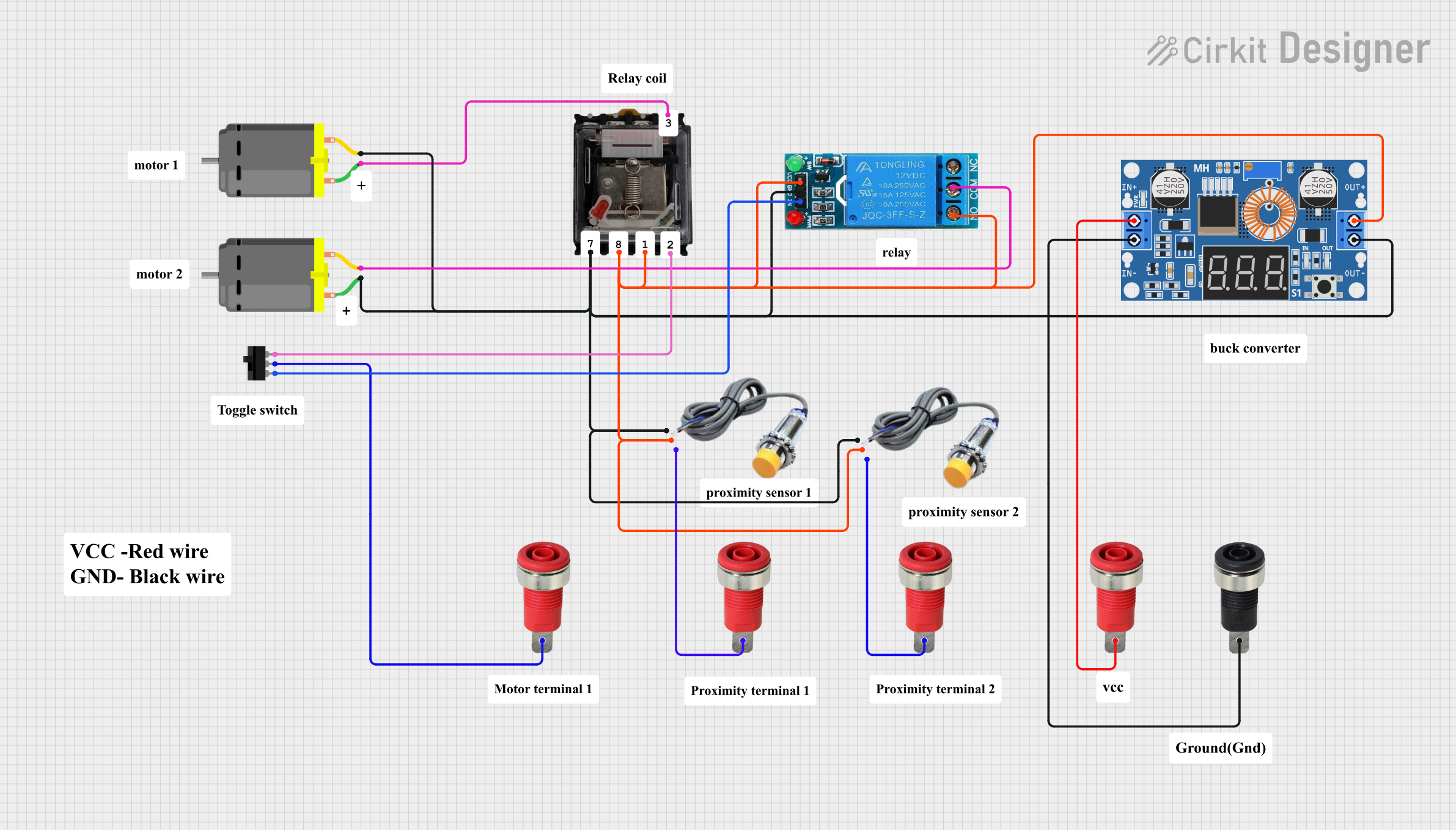
  1. Connect the input voltage to the IN+ and IN- pins, ensuring that the voltage is within the specified range.
  2. Connect the load to the OUT+ and OUT- pins.
  3. Adjust the output voltage by turning the onboard potentiometer. Use a multimeter to measure the output voltage while adjusting.
  4. If the current draw is close to or at 5A, ensure that the module is mounted on a heat sink to dissipate heat effectively.

Important Considerations and Best Practices

  • Always verify input and output voltages with a multimeter before connecting sensitive electronics.
  • Avoid adjusting the potentiometer while the module is under load to prevent voltage spikes.
  • For high-current applications, ensure adequate heat dissipation to prevent thermal shutdown or damage.
  • Use thick wires for high-current connections to minimize voltage drop and heat generation.

Troubleshooting and FAQs

Common Issues Users Might Face

  • Output voltage is not stable or does not match the setting: Ensure that the potentiometer is adjusted correctly and that the input voltage is stable and within the specified range.
  • Module overheats: Check if the current draw is too high or if adequate heat sinking is in place.
  • No output voltage: Verify connections and input voltage, and check for any signs of damage on the module.

Solutions and Tips for Troubleshooting

  • If the output voltage is unstable, re-adjust the potentiometer and check the input voltage stability.
  • For overheating issues, reduce the load current or improve heat dissipation with a larger heat sink or active cooling.
  • If there is no output voltage, double-check all connections and replace the module if it appears damaged.

FAQs

Q: Can I use the XL4015 to charge batteries? A: Yes, but ensure that the output voltage is set correctly for the battery type and that the charging current does not exceed the battery's specifications.

Q: How do I know if I need a heat sink? A: If the module is running hot to the touch or if you are drawing more than 2A continuously, it is recommended to use a heat sink.

Q: Is the output voltage fixed or adjustable? A: The output voltage is adjustable via the onboard potentiometer.

Q: Can I use this module with an Arduino UNO? A: Yes, you can use it to step down the voltage for an Arduino UNO or any other compatible device, but ensure the output voltage is set to 5V or the appropriate level for your device.

Example Arduino UNO Connection Code

// No specific code is required for the XL4015 when used with an Arduino UNO.
// The XL4015 is a standalone power module and does not interface directly with
// the Arduino's digital or analog pins. However, you can use the Arduino to
// monitor the output voltage of the XL4015 if desired.

void setup() {
  Serial.begin(9600);
  pinMode(A0, INPUT); // Connect the output voltage of XL4015 to A0
}

void loop() {
  int sensorValue = analogRead(A0);
  float voltage = sensorValue * (5.0 / 1023.0); // Convert the reading to voltage
  Serial.print("Output Voltage: ");
  Serial.println(voltage);
  delay(1000);
}

Note: The above code assumes that the output voltage of the XL4015 is within the 0-5V range that the Arduino can measure. If the voltage is higher, a voltage divider is required to bring the voltage into the measurable range.