How to Use Heltec Lora 32 v2: Examples, Pinouts, and Specs
Introduction
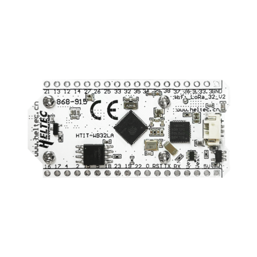
The Heltec LoRa 32 v2 is a compact development board designed for IoT applications and wireless sensor networks. It features an ESP32 microcontroller with integrated LoRa (Long Range) communication capabilities, making it ideal for low-power, long-range wireless communication. Additionally, the board includes an onboard OLED display for quick data visualization and debugging.
Explore Projects Built with Heltec Lora 32 v2
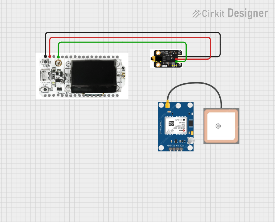
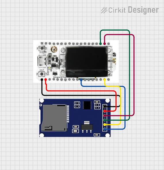
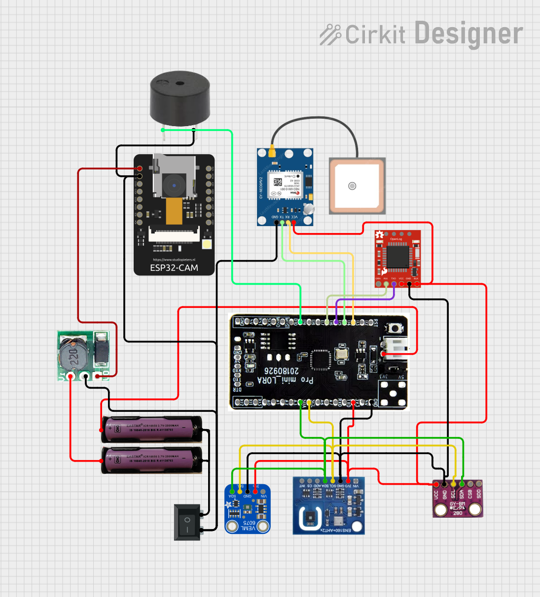
Explore Projects Built with Heltec Lora 32 v2
Common Applications and Use Cases
- Internet of Things (IoT) devices
- Wireless sensor networks
- Smart agriculture and environmental monitoring
- Home automation systems
- Remote data logging and telemetry
- Industrial automation
Technical Specifications
Key Technical Details
| Parameter | Specification |
|---|---|
| Microcontroller | ESP32 (dual-core, 32-bit, 240 MHz) |
| LoRa Module | Semtech SX1276 |
| Frequency Band | 433 MHz / 868 MHz / 915 MHz (region-dependent) |
| Flash Memory | 8 MB |
| SRAM | 520 KB |
| Operating Voltage | 3.3 V |
| Input Voltage Range | 5 V (via USB) or 3.7 V (via LiPo battery) |
| Communication Interfaces | UART, SPI, I2C, GPIO, ADC, DAC |
| OLED Display | 0.96-inch, 128x64 pixels, monochrome |
| Antenna Connector | IPEX (external antenna required) |
| Dimensions | 41 x 25 x 12 mm |
Pin Configuration and Descriptions
| Pin Number | Pin Name | Description |
|---|---|---|
| 1 | GND | Ground |
| 2 | 3V3 | 3.3 V power output |
| 3 | EN | Enable pin (active high) |
| 4 | GPIO0 | General-purpose I/O, boot mode selection |
| 5 | GPIO16 | General-purpose I/O |
| 6 | GPIO17 | General-purpose I/O |
| 7 | GPIO18 | General-purpose I/O |
| 8 | GPIO19 | General-purpose I/O |
| 9 | GPIO21 | I2C SDA (data line) |
| 10 | GPIO22 | I2C SCL (clock line) |
| 11 | GPIO23 | General-purpose I/O |
| 12 | GPIO25 | DAC1 (digital-to-analog converter) |
| 13 | GPIO26 | DAC2 (digital-to-analog converter) |
| 14 | GPIO27 | General-purpose I/O |
| 15 | GPIO32 | ADC1 (analog-to-digital converter) |
| 16 | GPIO33 | ADC2 (analog-to-digital converter) |
| 17 | GPIO34 | ADC3 (analog-to-digital converter, input only) |
| 18 | GPIO35 | ADC4 (analog-to-digital converter, input only) |
| 19 | VIN | Power input (5 V via USB or 3.7 V via battery) |
Usage Instructions
How to Use the Component in a Circuit
Powering the Board:
- Connect the board to a 5 V USB power source or use a 3.7 V LiPo battery via the JST connector.
- Ensure the external antenna is securely connected to the IPEX connector for proper LoRa communication.
Programming the Board:
- Install the Arduino IDE and add the ESP32 board support package.
- Select "Heltec ESP32 LoRa" as the board type in the Arduino IDE.
- Connect the board to your computer via USB and upload your code.
Connecting Peripherals:
- Use the GPIO pins for connecting sensors, actuators, or other peripherals.
- Use the I2C pins (GPIO21 for SDA and GPIO22 for SCL) for interfacing with I2C devices.
Using the OLED Display:
- The onboard OLED display is connected via I2C. Use the Heltec OLED library to display text or graphics.
LoRa Communication:
- Use the LoRa library to configure and send/receive data over long distances.
- Ensure the frequency band matches your region's regulations (e.g., 868 MHz for Europe, 915 MHz for the US).
Important Considerations and Best Practices
- Always connect the external antenna before powering the board to avoid damage to the LoRa module.
- Use a stable power source to prevent unexpected resets or malfunctions.
- Avoid exceeding the GPIO pin voltage limits (3.3 V max) to prevent damage to the microcontroller.
- When using the board in battery-powered applications, monitor the battery voltage to avoid over-discharge.
Example Code for Arduino UNO
Below is an example of how to send a simple message using LoRa communication:
#include <SPI.h>
#include <LoRa.h> // Include the LoRa library

#define SS 18    // LoRa module's chip select pin
#define RST 14   // LoRa module's reset pin
#define DIO0 26  // LoRa module's IRQ pin

void setup() {
  Serial.begin(9600); // Initialize serial communication
  while (!Serial);

  Serial.println("Initializing LoRa...");

  // Initialize LoRa module
  if (!LoRa.begin(915E6)) { // Set frequency to 915 MHz
    Serial.println("LoRa initialization failed!");
    while (1);
  }

  Serial.println("LoRa initialized successfully!");
}

void loop() {
  Serial.println("Sending message...");
  LoRa.beginPacket(); // Start a new LoRa packet
  LoRa.print("Hello, LoRa!"); // Add message to the packet
  LoRa.endPacket(); // Send the packet

  delay(5000); // Wait 5 seconds before sending the next message
}
Troubleshooting and FAQs
Common Issues and Solutions
The board does not power on:
- Ensure the USB cable is properly connected and functional.
- Check the battery connection if using a LiPo battery.
LoRa communication is not working:
- Verify that the external antenna is securely connected.
- Ensure the frequency band matches your region's regulations.
- Check for interference or obstacles between the transmitter and receiver.
OLED display is not showing anything:
- Confirm that the Heltec OLED library is installed and included in your code.
- Ensure the I2C pins (GPIO21 and GPIO22) are not being used by other devices.
The board is not recognized by the computer:
- Install the correct USB-to-serial driver for the Heltec LoRa 32 v2.
- Try a different USB cable or port.
FAQs
Can I use the Heltec LoRa 32 v2 without the OLED display?
Yes, the OLED display is optional and can be disabled in the code to save power.What is the maximum range of LoRa communication?
The range depends on environmental factors but can reach up to 10 km in open areas.Can I power the board with a 5 V power supply directly?
Yes, you can power the board via the VIN pin or USB port with a 5 V supply.Is the Heltec LoRa 32 v2 compatible with Arduino libraries?
Yes, it is compatible with most Arduino libraries, including those for LoRa and OLED.