How to Use ldr dfrobot v2: Examples, Pinouts, and Specs
Introduction
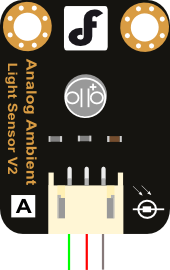
The LDR DFRobot V2 is a light-dependent resistor (LDR) that adjusts its resistance based on the intensity of light it receives. This component is ideal for light-sensing applications, enabling circuits to react to changes in ambient light levels. It is widely used in projects such as automatic lighting systems, light meters, and light-following robots. Its compact design and ease of use make it suitable for both beginners and advanced users.
Explore Projects Built with ldr dfrobot v2
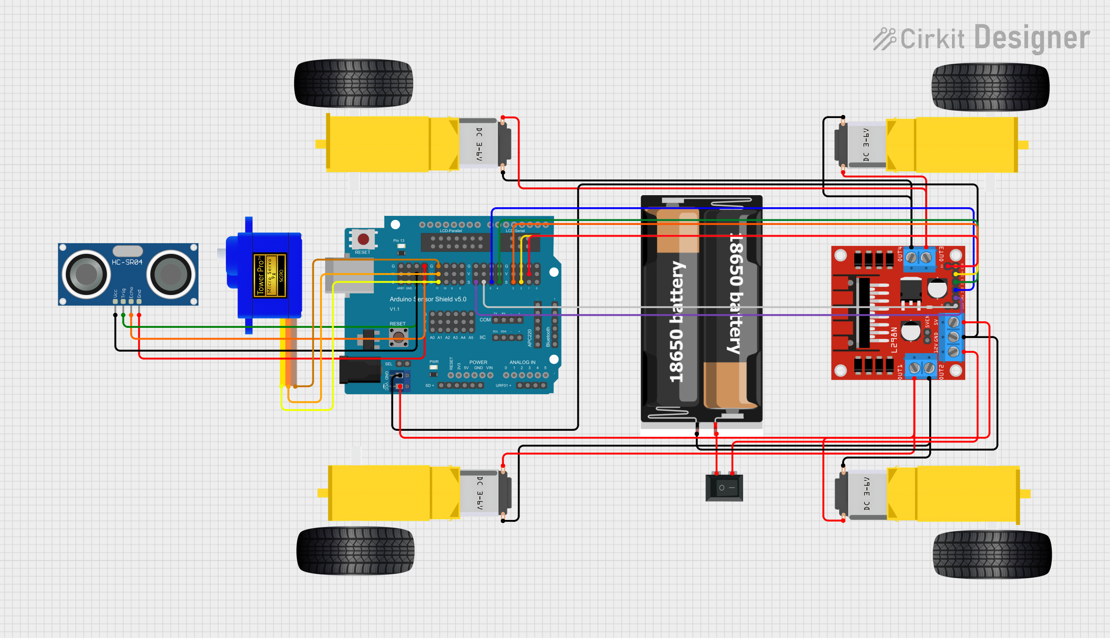
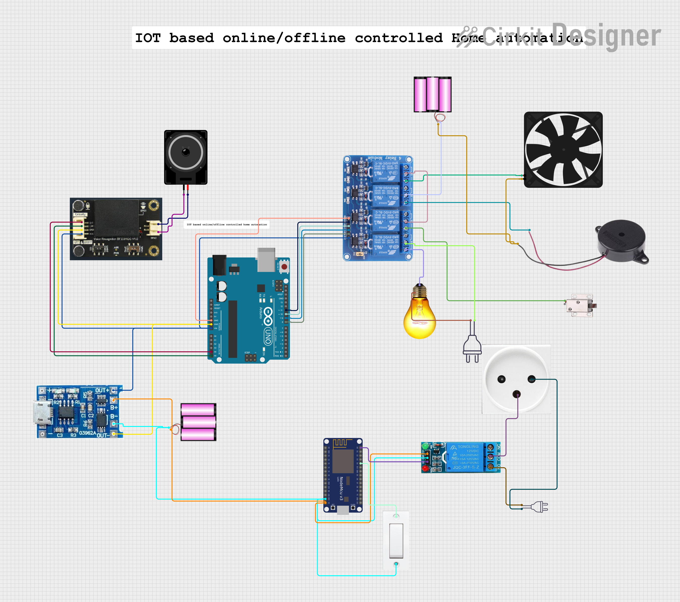
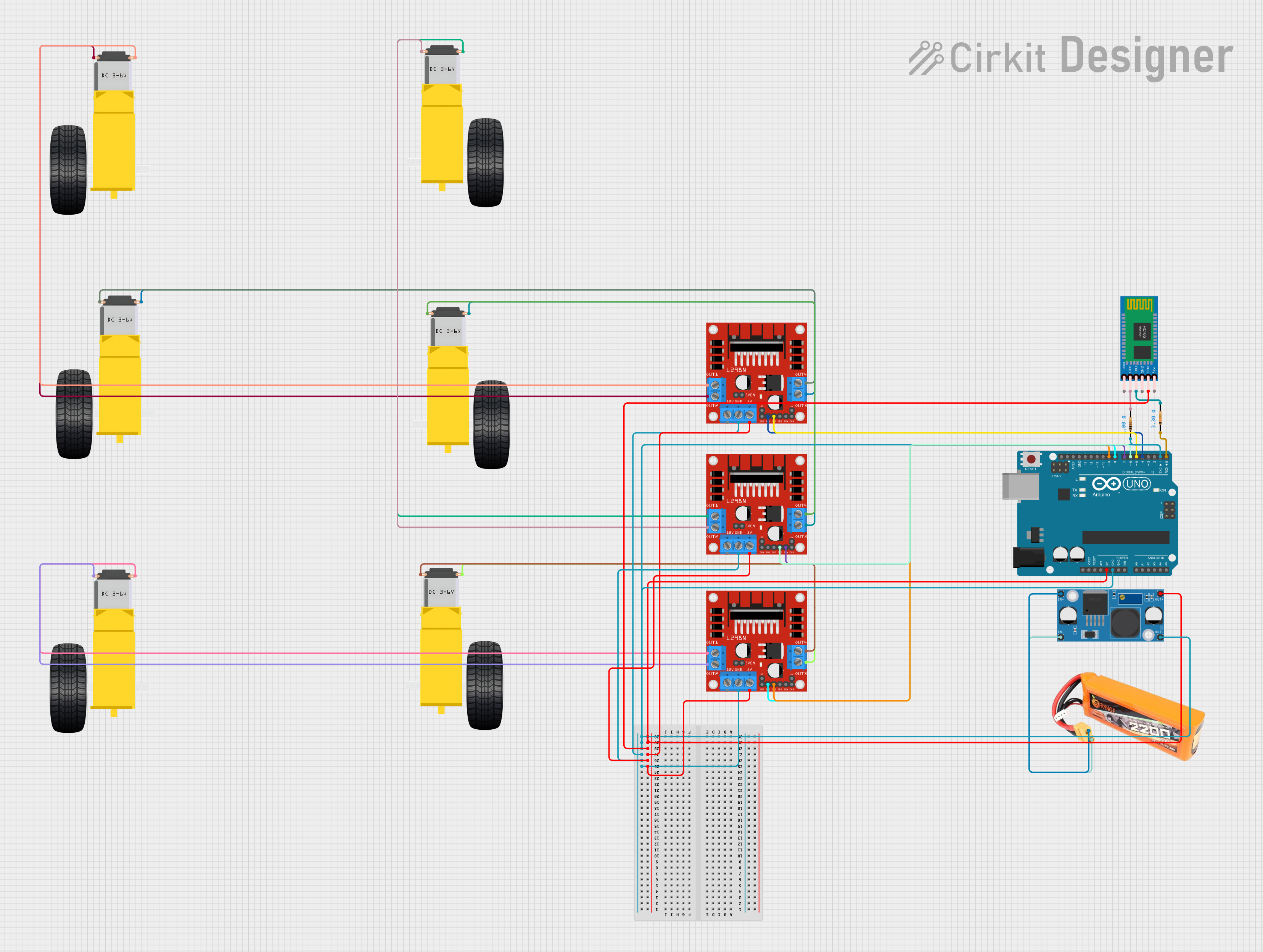
Explore Projects Built with ldr dfrobot v2
Technical Specifications
- Resistance Range: 10 kΩ to 1 MΩ (depending on light intensity)
- Operating Voltage: 3.3V to 5V
- Power Consumption: Low power
- Response Time: ~20ms (rise time), ~30ms (fall time)
- Operating Temperature: -30°C to 70°C
- Dimensions: 22mm x 30mm (module size)
Pin Configuration and Descriptions
The LDR DFRobot V2 module has three pins, as described in the table below:
| Pin Name | Description |
|---|---|
| VCC | Power supply input (3.3V to 5V) |
| GND | Ground connection |
| OUT | Analog output signal (light level) |
Usage Instructions
How to Use the Component in a Circuit
- Power the Module: Connect the
VCCpin to a 3.3V or 5V power source and theGNDpin to the ground of your circuit. - Read the Output: Connect the
OUTpin to an analog input pin of your microcontroller (e.g., Arduino UNO) to measure the light intensity. - Adjust Sensitivity: The module may include a potentiometer to adjust the sensitivity of the LDR. Turn the potentiometer clockwise or counterclockwise to fine-tune the response.
Important Considerations and Best Practices
- Avoid Direct Sunlight: Prolonged exposure to direct sunlight may degrade the LDR's performance over time.
- Use Proper Pull-Down Resistors: If the output signal is noisy, consider adding a pull-down resistor to stabilize the signal.
- Shield from Electrical Noise: Place the module away from high-frequency components to avoid interference.
- Calibrate for Accuracy: If precise light measurements are required, calibrate the module in the intended environment.
Example Code for Arduino UNO
The following code demonstrates how to use the LDR DFRobot V2 with an Arduino UNO to read light intensity and display the values in the Serial Monitor.
// Define the analog pin connected to the LDR module's OUT pin
const int ldrPin = A0;

void setup() {
  // Initialize the Serial Monitor for debugging
  Serial.begin(9600);
}

void loop() {
  // Read the analog value from the LDR module
  int lightLevel = analogRead(ldrPin);

  // Print the light level to the Serial Monitor
  Serial.print("Light Level: ");
  Serial.println(lightLevel);

  // Add a small delay to avoid flooding the Serial Monitor
  delay(500);
}
Code Explanation:
- The
ldrPinvariable specifies the analog pin connected to the LDR module. - The
analogRead()function reads the light intensity as an analog value (0-1023). - The
Serial.print()andSerial.println()functions display the light level in the Serial Monitor.
Troubleshooting and FAQs
Common Issues and Solutions
No Output or Incorrect Readings:
- Ensure the
VCCandGNDpins are properly connected to the power supply. - Verify that the
OUTpin is connected to the correct analog input pin on the microcontroller.
- Ensure the
Fluctuating or Noisy Readings:
- Add a capacitor (e.g., 0.1µF) between the
OUTpin and ground to filter noise. - Use a pull-down resistor to stabilize the output signal.
- Add a capacitor (e.g., 0.1µF) between the
LDR Not Responding to Light Changes:
- Check if the sensitivity potentiometer is set too high or too low.
- Ensure the LDR is not obstructed or covered.
FAQs
Q: Can the LDR DFRobot V2 detect specific light wavelengths?
A: No, the LDR is not wavelength-specific. It responds to general light intensity and is most sensitive to visible light.
Q: Can I use this module with a 3.3V microcontroller?
A: Yes, the module operates within a voltage range of 3.3V to 5V, making it compatible with 3.3V systems.
Q: How do I increase the accuracy of light measurements?
A: Calibrate the module in the target environment and use averaging techniques in your code to smooth out readings.
Q: Is the module suitable for outdoor use?
A: While it can be used outdoors, ensure it is protected from moisture and extreme temperatures to prevent damage.
By following this documentation, you can effectively integrate the LDR DFRobot V2 into your projects and troubleshoot any issues that arise.