How to Use TTL TO 485: Examples, Pinouts, and Specs
Introduction
The TTL to RS-485 converter is a versatile electronic component designed to convert TTL-level signals (typically 0–5V or 0–3.3V) into RS-485 differential signals. RS-485 is a robust communication standard widely used for long-distance and noise-resistant data transmission. This converter enables seamless communication between TTL-based devices, such as microcontrollers, and RS-485 networks.
Explore Projects Built with TTL TO 485


Explore Projects Built with TTL TO 485
Common Applications and Use Cases
- Industrial automation and control systems
- Long-distance communication between microcontrollers or sensors
- Building management systems (e.g., HVAC, lighting control)
- Serial communication in noisy environments
- Connecting Arduino, Raspberry Pi, or other TTL-based devices to RS-485 networks
Technical Specifications
Below are the key technical details of the TTL to RS-485 converter:
| Parameter | Value |
|---|---|
| Operating Voltage | 3.3V or 5V |
| Communication Standard | RS-485 |
| Baud Rate | Up to 115200 bps |
| Operating Temperature | -40°C to 85°C |
| Maximum Communication Distance | Up to 1200 meters (at lower baud rates) |
| Input Signal Level (TTL) | 0–3.3V or 0–5V |
| Output Signal Level (RS-485) | Differential signal (-7V to +12V) |
| Power Consumption | Low power consumption |
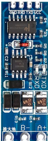
Pin Configuration and Descriptions
The TTL to RS-485 converter typically has the following pin configuration:
| Pin Name | Description |
|---|---|
| VCC | Power supply input (3.3V or 5V, depending on the module) |
| GND | Ground connection |
| TXD | TTL-level transmit data input (connect to the TX pin of the microcontroller) |
| RXD | TTL-level receive data output (connect to the RX pin of the microcontroller) |
| A (D+) | RS-485 differential signal positive terminal |
| B (D-) | RS-485 differential signal negative terminal |
| DE | Driver enable pin (active high, controls RS-485 transmission mode) |
| RE | Receiver enable pin (active low, controls RS-485 reception mode) |
Note: Some modules combine DE and RE into a single pin for simplified control.
Usage Instructions
How to Use the Component in a Circuit
- Power the Module: Connect the VCC pin to a 3.3V or 5V power source and the GND pin to ground.
- Connect TTL Signals:
- Connect the TXD pin of the converter to the TX pin of your microcontroller.
- Connect the RXD pin of the converter to the RX pin of your microcontroller.
- Connect RS-485 Signals:
- Connect the A (D+) and B (D-) pins to the RS-485 bus.
- Ensure proper termination resistors (typically 120Ω) are placed at both ends of the RS-485 bus for reliable communication.
- Control DE and RE Pins:
- Set DE high to enable transmission mode.
- Set RE low to enable reception mode.
- If DE and RE are combined, toggle the pin high for transmission and low for reception.
Important Considerations and Best Practices
- Termination Resistors: Always use termination resistors at both ends of the RS-485 bus to prevent signal reflections.
- Biasing Resistors: Add pull-up and pull-down resistors to the A and B lines to maintain a known idle state when no device is transmitting.
- Grounding: Ensure all devices on the RS-485 bus share a common ground to avoid communication errors.
- Baud Rate and Distance: Higher baud rates reduce the maximum communication distance. For long distances, use lower baud rates.
- Noise Immunity: RS-485 is designed for noisy environments, but proper shielding and grounding of cables further enhance performance.
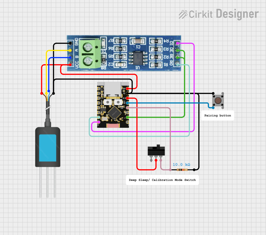
Example: Connecting to an Arduino UNO
Below is an example of how to use the TTL to RS-485 converter with an Arduino UNO:
Circuit Diagram
- Connect the VCC and GND pins of the converter to the 5V and GND pins of the Arduino.
- Connect the TXD pin of the converter to the Arduino's TX (pin 1).
- Connect the RXD pin of the converter to the Arduino's RX (pin 0).
- Connect the A (D+) and B (D-) pins to the RS-485 bus.
Arduino Code
// Example code for using TTL to RS-485 converter with Arduino UNO
// This code sends "Hello, RS-485!" over the RS-485 bus.

void setup() {
  Serial.begin(9600); // Initialize serial communication at 9600 baud
  delay(1000);        // Wait for the serial connection to stabilize
}

void loop() {
  Serial.println("Hello, RS-485!"); // Send data over RS-485
  delay(1000);                      // Wait 1 second before sending again
}
Note: If DE and RE are separate pins, you may need to control them using additional GPIO pins on the Arduino.
Troubleshooting and FAQs
Common Issues and Solutions
No Communication on RS-485 Bus:
- Verify that the A (D+) and B (D-) lines are correctly connected.
- Check for proper termination resistors at both ends of the RS-485 bus.
- Ensure all devices share a common ground.
Data Corruption or Noise:
- Use shielded twisted-pair cables for the RS-485 bus.
- Add biasing resistors to maintain a known idle state on the bus.
Module Not Powering On:
- Confirm that the VCC pin is receiving the correct voltage (3.3V or 5V).
- Check for loose or incorrect connections.
Incorrect Data Transmission:
- Ensure the baud rate and communication settings (e.g., parity, stop bits) match on all devices.
- Verify that DE and RE pins are being toggled correctly for transmission and reception.
FAQs
Q: Can I use this module with a 3.3V microcontroller?
A: Yes, the module supports both 3.3V and 5V logic levels. Ensure the VCC pin is connected to the appropriate voltage.
Q: What is the maximum number of devices I can connect to the RS-485 bus?
A: RS-485 supports up to 32 devices on a single bus. For more devices, use RS-485 repeaters.
Q: Do I need to manually control the DE and RE pins?
A: Some modules combine DE and RE into a single pin for simplified control. If separate, you must toggle them manually in your code.
Q: Can I use this module for half-duplex communication?
A: Yes, RS-485 is inherently a half-duplex protocol. Ensure proper control of the DE and RE pins to switch between transmission and reception.
By following this documentation, you can effectively integrate the TTL to RS-485 converter into your projects for reliable and long-distance communication.