How to Use L293D Motor Driver Module: Examples, Pinouts, and Specs
Introduction
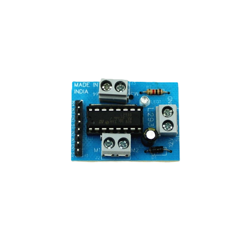
The L293D Motor Driver Module is a versatile integrated circuit designed to control DC motors and stepper motors. Manufactured by UG LAND INDIA, Electronic Spices, and GEOES INDIA, this module is widely used in robotics and automation projects. It allows for bidirectional control of up to two motors simultaneously, making it ideal for applications requiring precise motor control. The module also features built-in diodes for back EMF protection, ensuring safe and reliable operation.
Explore Projects Built with L293D Motor Driver Module


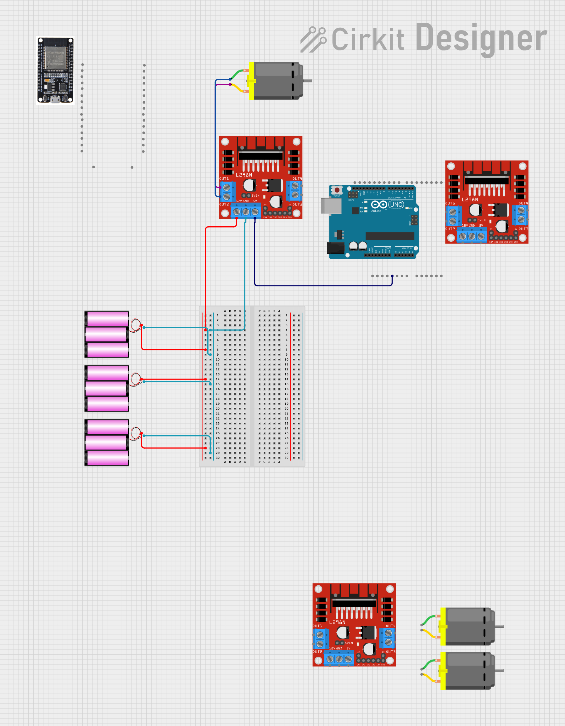
Explore Projects Built with L293D Motor Driver Module
Common Applications and Use Cases
- Robotics: Driving wheels or robotic arms
- Automation systems: Conveyor belts, automated doors
- DIY projects: Remote-controlled cars, drones
- Educational purposes: Learning motor control with microcontrollers like Arduino
Technical Specifications
Below are the key technical details of the L293D Motor Driver Module:
| Parameter | Value |
|---|---|
| Operating Voltage | 4.5V to 36V |
| Logic Voltage | 5V |
| Maximum Output Current | 600mA per channel |
| Peak Output Current | 1.2A per channel (non-continuous) |
| Number of Channels | 2 (can drive 2 motors) |
| Motor Type Supported | DC motors, stepper motors |
| Built-in Protection | Back EMF diodes |
| Operating Temperature | -40°C to +150°C |
Pin Configuration and Descriptions
The L293D Motor Driver Module has 16 pins. Below is the pin configuration:
| Pin Number | Pin Name | Description |
|---|---|---|
| 1 | Enable 1 (EN1) | Enables/Disables Motor 1 (High = Enabled, Low = Disabled) |
| 2 | Input 1 (IN1) | Input signal for Motor 1 (controls direction when combined with IN2) |
| 3 | Output 1 (OUT1) | Output to Motor 1 terminal |
| 4 | GND | Ground connection |
| 5 | GND | Ground connection |
| 6 | Output 2 (OUT2) | Output to Motor 1 terminal |
| 7 | Input 2 (IN2) | Input signal for Motor 1 (controls direction when combined with IN1) |
| 8 | Vcc2 (Motor V) | Motor power supply (4.5V to 36V) |
| 9 | Enable 2 (EN2) | Enables/Disables Motor 2 (High = Enabled, Low = Disabled) |
| 10 | Input 3 (IN3) | Input signal for Motor 2 (controls direction when combined with IN4) |
| 11 | Output 3 (OUT3) | Output to Motor 2 terminal |
| 12 | GND | Ground connection |
| 13 | GND | Ground connection |
| 14 | Output 4 (OUT4) | Output to Motor 2 terminal |
| 15 | Input 4 (IN4) | Input signal for Motor 2 (controls direction when combined with IN3) |
| 16 | Vcc1 (Logic V) | Logic power supply (typically 5V) |
Usage Instructions
How to Use the L293D Motor Driver Module in a Circuit
Power Connections:
- Connect the Vcc1 (Pin 16) to a 5V power supply for the logic circuit.
- Connect the Vcc2 (Pin 8) to the motor power supply (4.5V to 36V, depending on the motor's requirements).
- Connect all GND pins (Pins 4, 5, 12, 13) to the ground of the power supply.
Motor Connections:
- Connect the motor terminals to the output pins (OUT1, OUT2 for Motor 1 and OUT3, OUT4 for Motor 2).
Control Signals:
- Use the input pins (IN1, IN2 for Motor 1 and IN3, IN4 for Motor 2) to control the direction of the motors.
- Enable the motors by setting the enable pins (EN1, EN2) to HIGH.
Direction Control:
- For each motor, the direction is determined by the combination of the input signals:
- IN1 = HIGH, IN2 = LOW → Motor 1 rotates forward.
- IN1 = LOW, IN2 = HIGH → Motor 1 rotates backward.
- IN1 = IN2 → Motor 1 stops.
- For each motor, the direction is determined by the combination of the input signals:
PWM Speed Control:
- Connect a PWM signal to the enable pins (EN1, EN2) to control the speed of the motors.
Important Considerations and Best Practices
- Ensure the motor's current requirements do not exceed the module's maximum output current (600mA per channel).
- Use a heat sink if the module operates at high currents for extended periods.
- Always connect the ground of the motor power supply and the logic power supply to ensure proper operation.
- Use decoupling capacitors near the power supply pins to reduce noise.
Example: Connecting to an Arduino UNO
Below is an example of how to control a DC motor using the L293D Motor Driver Module and an Arduino UNO:
Circuit Connections
- Vcc1 (Pin 16) → Arduino 5V
- Vcc2 (Pin 8) → External motor power supply (e.g., 12V)
- GND (Pins 4, 5, 12, 13) → Common ground
- IN1 (Pin 2) → Arduino Digital Pin 2
- IN2 (Pin 7) → Arduino Digital Pin 3
- EN1 (Pin 1) → Arduino Digital Pin 9 (PWM for speed control)
- OUT1, OUT2 → DC motor terminals
Arduino Code
// Define motor control pins
const int EN1 = 9;  // Enable pin for Motor 1
const int IN1 = 2;  // Input 1 for Motor 1
const int IN2 = 3;  // Input 2 for Motor 1

void setup() {
  // Set motor control pins as outputs
  pinMode(EN1, OUTPUT);
  pinMode(IN1, OUTPUT);
  pinMode(IN2, OUTPUT);
}

void loop() {
  // Rotate motor forward
  digitalWrite(IN1, HIGH);  // Set IN1 HIGH
  digitalWrite(IN2, LOW);   // Set IN2 LOW
  analogWrite(EN1, 128);    // Set speed to 50% (PWM value: 128 out of 255)
  delay(2000);              // Run for 2 seconds

  // Stop motor
  digitalWrite(IN1, LOW);   // Set IN1 LOW
  digitalWrite(IN2, LOW);   // Set IN2 LOW
  delay(1000);              // Wait for 1 second

  // Rotate motor backward
  digitalWrite(IN1, LOW);   // Set IN1 LOW
  digitalWrite(IN2, HIGH);  // Set IN2 HIGH
  analogWrite(EN1, 200);    // Set speed to ~78% (PWM value: 200 out of 255)
  delay(2000);              // Run for 2 seconds

  // Stop motor
  digitalWrite(IN1, LOW);   // Set IN1 LOW
  digitalWrite(IN2, LOW);   // Set IN2 LOW
  delay(1000);              // Wait for 1 second
}
Troubleshooting and FAQs
Common Issues and Solutions
Motor Not Spinning:
- Ensure the enable pin (EN1 or EN2) is set to HIGH or connected to a PWM signal.
- Verify the motor power supply (Vcc2) is connected and within the required voltage range.
Motor Spins in the Wrong Direction:
- Check the input pin configuration (IN1, IN2 or IN3, IN4). Swap the HIGH/LOW signals to reverse the direction.
Overheating:
- Ensure the motor's current does not exceed 600mA per channel.
- Use a heat sink or cooling fan if necessary.
No Response from the Module:
- Verify all ground connections are properly connected.
- Check the logic power supply (Vcc1) and ensure it is 5V.
FAQs
Can I control stepper motors with the L293D? Yes, the L293D can control stepper motors by driving the coils in sequence. Refer to the stepper motor's datasheet for the correct sequence.
What happens if I exceed the current limit? Exceeding the current limit may damage the IC. Use motors within the specified current range or add external current-limiting resistors.
Can I use the L293D with a 3.3V microcontroller? The L293D requires a 5V logic supply (Vcc1). Use a level shifter to interface with