Cirkit Designer
Your all-in-one circuit design IDE
Home /
Component Documentation
How to Use 7 Segment Display(4 Digit): Examples, Pinouts, and Specs
Introduction
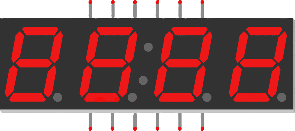
A 7-segment display with 4 digits is an electronic component used to display numerical information. Each digit consists of 7 LEDs arranged in a figure-8 pattern, allowing for the display of numbers 0-9. This component is widely used in digital clocks, electronic meters, and other devices that require a simple, numeric display.
Explore Projects Built with 7 Segment Display(4 Digit)
Arduino UNO 4-Digit 7-Segment Display Counter
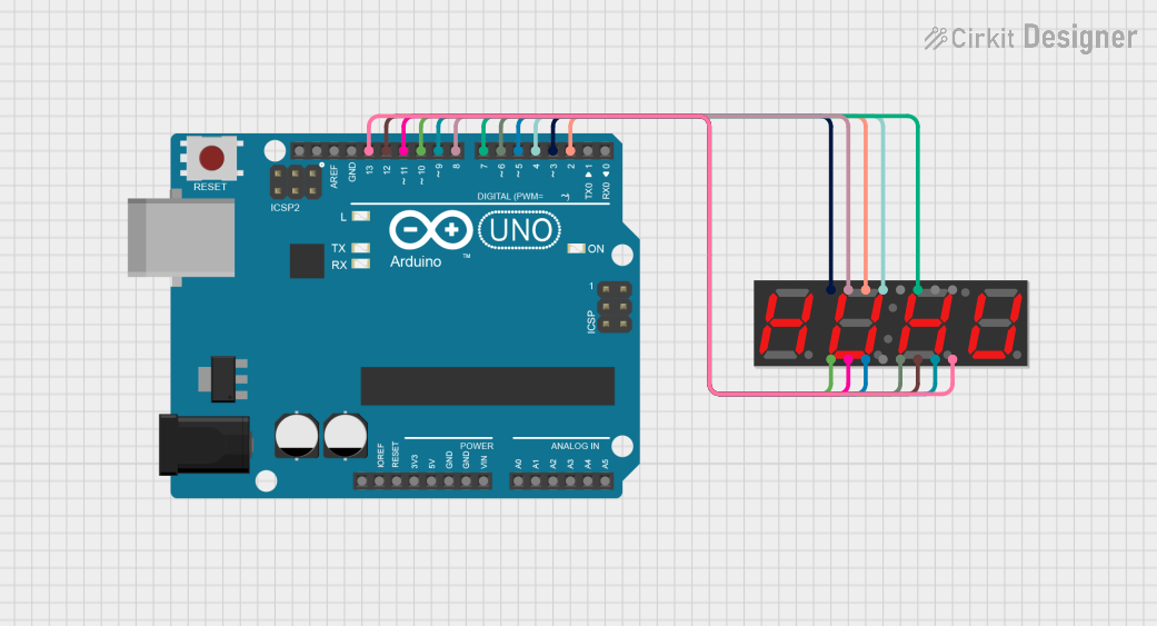
This circuit uses an Arduino UNO to control a 4-digit 7-segment display. The Arduino is programmed to sequentially display the numbers 1, 2, 3, and 4 on the display by driving the appropriate segments and digits.
Arduino UNO 4-Digit Seven Segment Display Counter
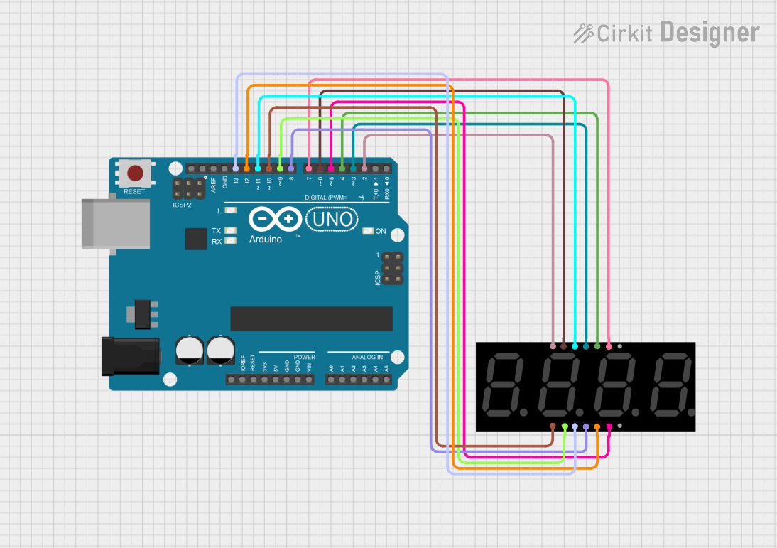
This circuit uses an Arduino UNO to control a 4-digit seven-segment display. The Arduino runs a program that counts up in deci-seconds and displays the count on the seven-segment display using the SevSeg library.
Arduino UNO Controlled LED and 7-Segment Display Circuit
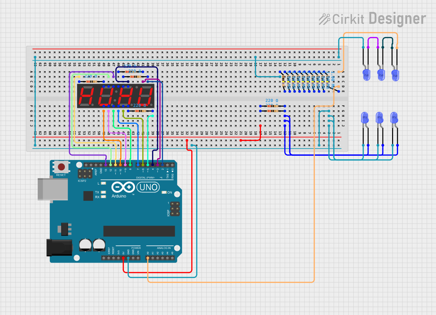
This circuit features an Arduino UNO controlling multiple blue LEDs and a 4-digit 7-segment display. The LEDs are configured with current-limiting resistors, and the display is interfaced with the Arduino for potential numeric or character output. The provided code for the Arduino is a template without specific functionality.
Arduino UNO Controlled Seven Segment Display
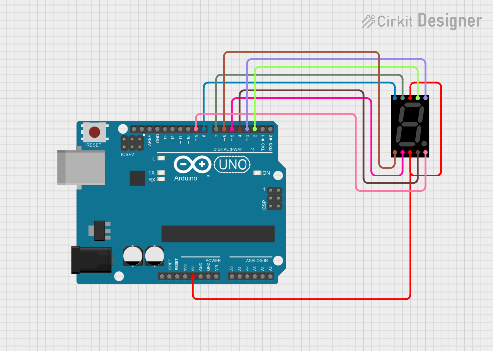
This circuit utilizes an Arduino UNO to control a seven-segment display, allowing it to display digits from 0 to 9 in a sequential manner. The Arduino is programmed to set the appropriate pins high or low to illuminate the segments of the display, creating the desired digit patterns. The display updates every second, providing a simple visual output for numerical representation.
Explore Projects Built with 7 Segment Display(4 Digit)
Arduino UNO 4-Digit 7-Segment Display Counter
This circuit uses an Arduino UNO to control a 4-digit 7-segment display. The Arduino is programmed to sequentially display the numbers 1, 2, 3, and 4 on the display by driving the appropriate segments and digits.
Arduino UNO 4-Digit Seven Segment Display Counter
This circuit uses an Arduino UNO to control a 4-digit seven-segment display. The Arduino runs a program that counts up in deci-seconds and displays the count on the seven-segment display using the SevSeg library.
Arduino UNO Controlled LED and 7-Segment Display Circuit
This circuit features an Arduino UNO controlling multiple blue LEDs and a 4-digit 7-segment display. The LEDs are configured with current-limiting resistors, and the display is interfaced with the Arduino for potential numeric or character output. The provided code for the Arduino is a template without specific functionality.
Arduino UNO Controlled Seven Segment Display
This circuit utilizes an Arduino UNO to control a seven-segment display, allowing it to display digits from 0 to 9 in a sequential manner. The Arduino is programmed to set the appropriate pins high or low to illuminate the segments of the display, creating the desired digit patterns. The display updates every second, providing a simple visual output for numerical representation.
Technical Specifications
Key Technical Details
| Parameter | Value |
|---|---|
| Operating Voltage | 3.3V - 5V |
| Current per Segment | 10-20mA |
| Power Consumption | 140mW (max) |
| Number of Digits | 4 |
| Segment Configuration | Common Anode or Common Cathode |
| Operating Temperature | -40°C to +85°C |
Pin Configuration and Descriptions
Common Anode Configuration
| Pin Number | Description |
|---|---|
| 1 | Digit 1 Common Anode |
| 2 | Segment E |
| 3 | Digit 2 Common Anode |
| 4 | Segment D |
| 5 | Segment C |
| 6 | Digit 3 Common Anode |
| 7 | Segment DP (Decimal Point) |
| 8 | Segment B |
| 9 | Segment A |
| 10 | Digit 4 Common Anode |
| 11 | Segment F |
| 12 | Segment G |
Common Cathode Configuration
| Pin Number | Description |
|---|---|
| 1 | Digit 1 Common Cathode |
| 2 | Segment E |
| 3 | Digit 2 Common Cathode |
| 4 | Segment D |
| 5 | Segment C |
| 6 | Digit 3 Common Cathode |
| 7 | Segment DP (Decimal Point) |
| 8 | Segment B |
| 9 | Segment A |
| 10 | Digit 4 Common Cathode |
| 11 | Segment F |
| 12 | Segment G |
Usage Instructions
How to Use the Component in a Circuit
- Identify the Configuration: Determine whether your 7-segment display is common anode or common cathode.
- Connect the Digits: Connect the common pins (anode or cathode) of each digit to the appropriate control pins on your microcontroller.
- Connect the Segments: Connect each segment pin (A-G and DP) to the corresponding output pins on your microcontroller.
- Current Limiting Resistors: Use current limiting resistors (typically 220Ω to 1kΩ) in series with each segment to prevent excessive current draw.
- Multiplexing: For a 4-digit display, use multiplexing to control each digit individually. This involves rapidly switching between digits to create the illusion of a continuous display.
Important Considerations and Best Practices
- Power Supply: Ensure your power supply can handle the total current draw of the display.
- Brightness Control: Adjust the current limiting resistors to control the brightness of the display.
- Heat Dissipation: Be mindful of heat dissipation, especially if the display is used continuously.
- Code Efficiency: Optimize your code to handle multiplexing efficiently, reducing flicker and power consumption.
Example Code for Arduino UNO
// Define segment pins
const int segmentPins[] = {2, 3, 4, 5, 6, 7, 8, 9}; // A, B, C, D, E, F, G, DP
// Define digit pins
const int digitPins[] = {10, 11, 12, 13}; // Digit 1, 2, 3, 4

// Digit patterns for numbers 0-9
const byte digitPatterns[10] = {
  0b00111111, // 0
  0b00000110, // 1
  0b01011011, // 2
  0b01001111, // 3
  0b01100110, // 4
  0b01101101, // 5
  0b01111101, // 6
  0b00000111, // 7
  0b01111111, // 8
  0b01101111  // 9
};

void setup() {
  // Set segment pins as outputs
  for (int i = 0; i < 8; i++) {
    pinMode(segmentPins[i], OUTPUT);
  }
  // Set digit pins as outputs
  for (int i = 0; i < 4; i++) {
    pinMode(digitPins[i], OUTPUT);
  }
}

void loop() {
  // Display the number 1234
  displayNumber(1234);
}

void displayNumber(int number) {
  for (int i = 0; i < 4; i++) {
    int digit = number % 10; // Get the last digit
    number /= 10; // Remove the last digit

    // Set the digit pattern
    setDigitPattern(digitPatterns[digit]);

    // Activate the current digit
    digitalWrite(digitPins[i], LOW);
    delay(5); // Short delay for multiplexing
    digitalWrite(digitPins[i], HIGH);
  }
}

void setDigitPattern(byte pattern) {
  for (int i = 0; i < 8; i++) {
    digitalWrite(segmentPins[i], (pattern >> i) & 0x01);
  }
}
Troubleshooting and FAQs
Common Issues Users Might Face
- Display Not Lighting Up: Check the power supply and ensure all connections are secure.
- Incorrect Digits Displayed: Verify the pin connections and ensure the correct digit patterns are used.
- Flickering Display: Adjust the multiplexing delay and ensure efficient code execution.
- Dim Display: Check the current limiting resistors and power supply voltage.
Solutions and Tips for Troubleshooting
- Check Connections: Ensure all wires and connections are secure and correctly placed.
- Verify Code: Double-check your code for any errors or incorrect pin assignments.
- Use a Multimeter: Measure the voltage and current to ensure they are within the specified range.
- Consult Datasheets: Refer to the datasheet of your specific 7-segment display for detailed information.
By following this documentation, you should be able to effectively use a 7-segment display with 4 digits in your projects. Whether you are a beginner or an experienced user, this guide provides the necessary information to get started and troubleshoot common issues.